
Introduction: The key of magnetic beads and inductors in EMI and EMC circuits is to suppress high-frequency conducted interference signals, and also to suppress inductors. However, from the principle point of view, the magnetic bead can be equivalent to an inductor, which is equivalent to a certain difference, the biggest difference is that the inductor coil has a distributed capacitance. Therefore, an inductor is equivalent to an inductor in parallel with a distributed capacitor.
Magnetic beads and inductors in solving EMI and EMC aspects and what role, first of all let's look at the difference between magnetic beads and inductors, inductors is a property of closed loop, mostly used for power filter loop, and magnetic beads are mainly used for signal loop, for EMC countermeasures Magnetic beads are mainly used to suppress electromagnetic radiation interference, and inductors for this aspect is focused on suppressing conductive interference. Magnetic beads are used to absorb ultra-high frequency signals, like some RF circuits, PLL, oscillating circuits, including ultra-high frequency memory circuits (DDR SDRAM,RAMBUS, etc.) need to add magnetic beads in the power input part, both can be used to deal with EMC, EMI problems.
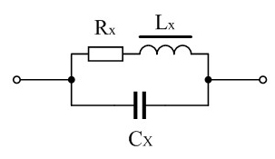
The key of magnetic beads and inductors in EMI and EMC circuits is to suppress high-frequency conducted interference signals, and also to suppress inductors. However, from the principle point of view, the magnetic bead can be equivalent to an inductor, which is equivalent to a certain difference, the biggest difference is that the inductor coil has a distributed capacitance. Therefore, an inductor is equivalent to an inductor in parallel with a distributed capacitor. As shown in Figure 1. In Figure 1, LX is the equivalent inductance (ideal electrical inductance) of the inductor coil, RX is the equivalent resistance of the coil, and CX is the distributed capacitance of the inductor.
If we want to further increase the suppression frequency, then the inductor we finally choose will have to be its minimum limit value, only 1 circle or less than 1 circle. Magnetic bead, that is, through the core inductor, is an inductor with a number of turns less than 1 turn. However, the distribution capacitance of the through-core inductor is several times to dozens of times smaller than that of the single-turn inductor, so the through-core inductor operates at a higher frequency than the single-turn inductor.
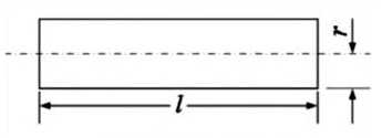
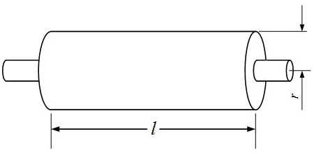
The inductance of the core inductance is generally relatively small, about between a few micro heng to dozens of micro heng, the size of the inductance is related to the size and length of the wire in the core inductance, and the cross-sectional area of the magnetic bead, but the largest relationship with the magnetic bead inductance is also calculated the relative magnetic permeability of the magnetic bead Uy. Figure 3 and Figure 4 are the schematic diagram of the guide wire and the through-core inductance respectively. When calculating the through-core inductance, the inductance of a circular straight wire should be calculated first, and then the inductance of the through-core inductance can be obtained by multiplying the calculation result by the relative magnetic permeability of the magnetic bead.
In addition, when the working frequency of the through-core inductor is very high, eddy currents will be generated in the magnetic bead, which is equivalent to the permeability of the through-core inductor to reduce, at this time, we generally use effective permeability. Effective permeability is the relative permeability of a magnetic bead at a certain operating frequency. However, since the operating frequency of the magnetic bead is only a range, the average magnetic permeability is used in practical applications。
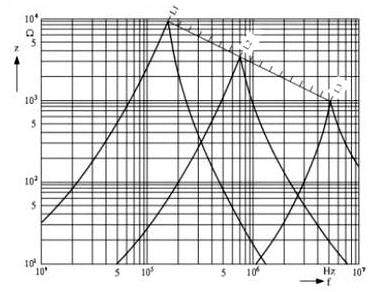
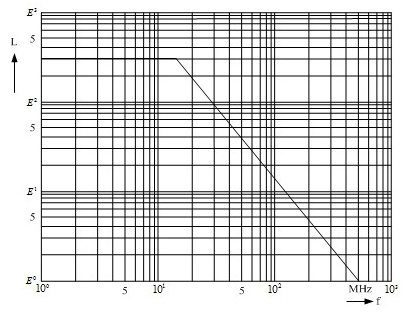
At low frequencies, the relative permeability of the general magnetic bead is very large (greater than 100), but at high frequencies, its effective permeability is only a fraction of the relative permeability, or even a few tens of one. Therefore, the magnetic bead also has the problem of cutoff frequency, the so-called cutoff frequency, is to make the effective magnetic permeability of the magnetic bead to close to 1 when the operating frequency fc, at this time the magnetic bead has lost an inductance. Generally, the cutoff frequency fc of magnetic beads is between 30~300MHz, and the cutoff frequency is related to the material of magnetic beads, and the higher the magnetic permeability of the magnetic core material, the lower the cutoff frequency fc, because the low frequency magnetic core material eddy current loss is relatively large. When the user is designing the circuit, he can ask the supplier of the magnetic core material to provide the test data of the operating frequency and effective permeability of the magnetic core, or the curve diagram of the core inductance under different operating frequencies. Figure 5 shows the frequency curve of the through-core inductor.
The advantage of using magnetic beads for electromagnetic shielding is that magnetic beads do not need to be grounded, which can eliminate the trouble of grounding the shielding line. Using magnetic beads as electromagnetic shielding, for double wires, it is also equivalent to connecting a common mode suppression inductor in the line, which has a strong suppression effect on common mode interference signals.
From the above we can understand that magnetic beads and inductors in EMC, EMI circuit can play a role in the suppression, mainly the suppression of the different aspects, and inductors in the high-frequency resonance can not be re-inductor role, first must understand the two ways of EMI, namely: radiation and conduction, different ways to use different suppression methods. The former uses magnetic beads, the latter uses inductors. What we also need to pay attention to is the connection position of the common mode suppression inductor and the Y capacitor. What is the common mode suppression inductor, that is, the inductor in series between the ground wire or other input and output lines, this inductor is called the common mode suppression inductor. One end of the common mode suppression inductor is connected with the ground wire (common end) in the machine, and the other end is connected with a Y capacitor. The other end of the Y capacitor is connected to the earth. This is the most effective way to suppress conducted interference.
免责声明: 本文章转自其它平台,并不代表本站观点及立场。若有侵权或异议,请联系我们删除。谢谢! Disclaimer: This article is reproduced from other platforms and does not represent the views or positions of this website. If there is any infringement or objection, please contact us to delete it. thank you! |

WeChat Official Account

WeChat Service
 Email
Email QQ
QQ 13823761625
