
Introduction:In order to obtain higher fidelity of audio system, this paper introduces a new concept. Many systems, especially those used in the home theater/mini band market, are careful to add distortion to the output signal. While this may seem counterintuitive to common sense, there are reasons why designers consider doing this.
THD (total harmonic distortion) is an indicator of the harmonic distortion of a signal, expressed as the ratio of the sum of the power of all harmonic components to the power of the fundamental frequency signal. The lower total harmonic distortion allows devices such as speakers, electronic amplifiers, or microphones to produce more accurate, less harmonic output signals that are close to the original sampled signal.
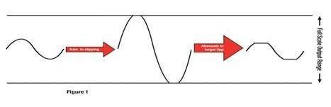
In order to obtain higher fidelity of audio system, this paper introduces a new concept. Many systems, especially those used in the home theater/mini band market, are careful to add distortion to the output signal. While this may seem counterintuitive to common sense, there are reasons why designers consider doing this. The main purpose of this technique is to maximize the average power output while limiting the occurrence of peaks.
Some customers use the same power amplifier IC for a range of products. This allows them to purchase a single device in larger quantities, reducing costs and simplifying inventory. They may use a low-power source to save costs. The customer will use a closed-loop, fixed-gain amplifier with a small power supply. It limits the output voltage swing (by limiting the output), which protects the low-power supply from overcurrent state damage. However, a simple attenuator can make the system quieter. Distorting the output slightly greatly increases the perceived RMS power. Be careful when determining the degree of increased distortion, do not increase too much!
For other customers, limiting the voltage output of their signal can help limit speaker drift. However, caution should be exercised in this case, as the high RMS power entering the speaker may cause reliability issues.
In digital processing systems, THD can be introduced into the signal by saturating the digital sample. That is, use sufficient gain to push the most significant bit beyond the digital sampling size. For example, you have a 24-bit word and your sample is 0x900000. With 12 Db gain, the highest audio bit exceeds the most significant bit (MSB) of the sample.
After that, dial down the data to the desired audio output level. Therefore, it can be summarized as:
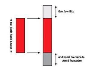
At the top, a total of 9 bits are used to prevent accidental saturation of audio data. For example, if you use a 24-dB turbocharged equalizer (EQ) and you input a "full range" 16-bit word, you may unintentionally saturate the signal, i.e. increase distortion, which is the opposite of what we are trying to do.
There is an amplitude loss when clipping, so THD (after) may allow a small amount of gain through the THD manager. 10% distortion clipping results in an output level loss of about -1dB.
In our example, the system has a 9.23 audio path. We want to produce 10%THD at -12 dB output. The average input is -10 dBFS (-10 dB reference 24-bit full range audio source).
We need to zoom to full range and above (" overflow bit "9 bits). So, in a booster module, we add 10 dB to the original source to reach full range, and later add another 27dB to fill the 9 overflow bits. Now, increase the 3dB gain to clipper the signal. In total, we need to increase the gain by 40dB.
Now we have a signal that fills the audio path MSB and asks for a cut so that the output is at -12 dB. This means that cutting 39dB. Produces an output with 10% distortion and an output level of -12 dB. Look! We have now increased the RMS power at -12 dB output (by increasing distortion) and made the work of both the power supply and the speaker much easier.
免责声明: 本文章转自其它平台,并不代表本站观点及立场。若有侵权或异议,请联系我们删除。谢谢! Disclaimer: This article is reproduced from other platforms and does not represent the views or positions of this website. If there is any infringement or objection, please contact us to delete it. thank you! |

WeChat Official Account

WeChat Service
 Email
Email QQ
QQ 13823761625
