
The author of this article
Victor Khasiev
Senior application engineer for power products
Linear Technology Corporation (now part of Analog Devices)
introduction
In terms of fully functional lithium-ion battery chargers, the main obstacle encountered by some designers is the lack of automatic or autonomous triggering function. For example, the controller does provide C/10 current detection, but does not interrupt the charging process when the charging current drops to a C/10 value. It also lacks the automatic restart required for a fully qualified charger.
The LTC4012 is a very popular chip used to charge lithium-ion batteries in a variety of applications. This controller provides grid drive and current detection inputs to establish a power link for a step-down topology. The LTC4012 also provides control signals, such as the state of charge and the presence of the adapter. The device also offers a range of useful functions, which are detailed in its data sheet.
In applications that do not use the CPU, designers either simply refuse to use the LTC4012 or develop their own solutions, which in some cases is not enough. For example, some designers may use a resistor on the PROG pin to detect the charging current, but connecting the PROG pin to a low-cost, low-impedance buffer will fundamentally distort the measurement.
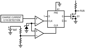
The purpose of this article is to illustrate a simple automatic restart solution that does not use PROG pins and uses logic signals for C/10 current detection. This detection is based on the "digital C/10 indicator" introduced in the LTC4012 data sheet, as shown in the block diagram.
Automatic restart circuit block diagram
The block diagram of the aforementioned circuit is shown in Figure 1. The circuit is based on a D flip-flop. As the charge current drops to the pre-set C/10, the D flip-flop clock changes to high, and the external transistor Q1 pulls the RUN pin to ground and turns off the LTC4012. The battery is charged. The voltage is close to maximum. As the charger is turned off, the battery begins to discharge, and eventually the minimum voltage is reached, the D trigger is cleared to zero, and then the Q1 is turned off, and the charging cycle is repeated.
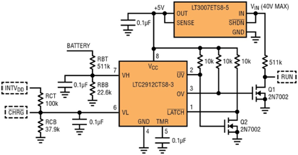
The test is 12V, 3000mA/h lithium-ion battery. The battery is charged by a charger mounted on the DC1256A demo circuit board using the LTC4012-2. The charger is controlled by the automatic restart circuit shown in Figure 2.
If the battery is charged, then the voltage on the VH input of the LTC2912-3 is higher than 0.5V and the /UV output is high. Q2 is on, the /LATCH pin is low, and the output OV is locked at a high level. Accordingly, Q1 is on and LTC4012 is in off mode. As long as the /LATCH pin is low and the OV lock is high, the LTC4012 remains in the off state.
Finally, the battery voltage begins to drop due to self-discharge or already loaded. When the battery voltage drops below 12V, the VH pin voltage (resistor divider RBT/RBB) drops below 0.5V, and the /UV output state changes from high to low. Q2 is then disconnected, thus clearing the block. The signal OV state becomes low, Q1 is disconnected, and the charging process starts.
During charging, the LTC4012's /CHRG pin is in a low impedance state, which connects the VL pin to GND. As the charge current drops to C/10, the /CHRG pin changes state and the voltage on the VL pin rises. When the voltage on this pin reaches 0.5V (resistor divider RCT/RCB), the OV pin's state changes from low to high, Q1 is switched on, RUN pin is pulled down, and LTC4012 enters shutdown mode. The /LATCH pin is low, and U1 locks the OV to high until the battery voltage drops again to 12V and the process begins to repeat. The proposed circuit is interlinked with the LTC4012, with the corresponding pins surrounded by dashed lines to distinguish them from the pins of the LTC2912 U1.
Current verification and measurement
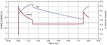
To verify circuit function, connect a data logger to the charger-battery system. Sample and store the battery voltage and current. To facilitate the self-discharge of the battery and shorten the discharge time, connect a 100Ω resistor between the battery terminals. The resulting graph is shown in Figure 3. At the beginning of the cycle, the input voltage VIN is disconnected, the battery is discharged, and a "negative" current is provided to the load. Then, after adding the VIN, the charging cycle starts, and the "positive" charging current flows into the battery. When the battery is fully charged, the charger is turned off and the battery begins to self-discharge. When the battery voltage reaches the minimum, the charger is switched on and the cycle repeats itself.
Conclusion
The circuit described in this paper is relatively simple, and the application based on this circuit can be used as an important accessory for the very popular lithium-ion battery charger LTC4012. This circuit enables automatic restart by using a single voltage monitor LTC2912-3, eliminating the need for a rather expensive digital control system.
免责声明: 本文章转自其它平台,并不代表本站观点及立场。若有侵权或异议,请联系我们删除。谢谢! Disclaimer: This article is reproduced from other platforms and does not represent the views or positions of this website. If there is any infringement or objection, please contact us to delete it. thank you! |

WeChat Official Account

WeChat Service
 Email
Email QQ
QQ 13823761625
