
While 12V lead-acid batteries are still the primary source of power for cars, new automotive applications require higher voltages, such as mainline audio power amplifiers and window defrosters. To address these high voltage applications, a new generation of AEC-Q100 certified synchronous boost controllers has emerged. These controllers are designed to boost the 12V battery voltage, withstand voltage spikes up to 60V, and provide the reliability required for new models.
This paper explores a pair of commonly used two-phase 55V synchronous boost controllers that can efficiently generate 24V, 36V, or 48V power rails in automotive environments with only 12V power supply. We will explore some of their key integration features, including a wide range of protection features, to optimize the solution to reduce costs and improve efficiency, safety and reliability. We will also discuss an integrated PMBus interface that provides advanced control, telemetry and diagnostic capabilities and simplifies the task of meeting the ISO 26262 standard.
Boost the 12V battery
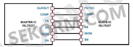
An ongoing challenge for system designers is how to achieve greater power efficiency while minimizing board space. The ISL78227 and ISL78229 55V synchronous boost controllers address this issue by integrating an advanced FET driver that adaptively adjusts the switching time to prevent cross conduction while simplifying the power stage design. The controller is in a two-phase configuration that reduces ripple current and allows for the use of smaller input and output capacitors, thereby reducing board footprint. Two controllers can be used in parallel, extending the number of phases to four to support higher power output levels.
The ISL78227 and ISL78229 with PMBus interfaces can operate over a wide frequency range, as low as 50kHz or up to 1.1MHz, and can be configured to optimize the operating frequency for increased efficiency or minimal board space by using smaller external components. They include a number of features designed to maximize efficiency, which is important because a 400W load will pull from a 12V battery to a peak current of more than 30A.
Synchronous FETs for output rectification
It is common for buck converters to use FETs instead of diodes for output rectifier functions because most buck converters offer low output voltages. In this configuration, the voltage drop at both ends of the rectifier element accounts for a high proportion of the power loss of the output voltage. Replacing the output rectifier diode with a synchronous FET can be turned on and off at the right time, greatly improving efficiency. This is because the FET loss is usually a small fraction of the loss of the rectifier diode. In buck converters, synchronous FETs are ground-referenced, so the drive circuit is relatively simple.
The simultaneous FET provides benefits for the boost configuration. In boost converter applications, the output voltage is usually several times the input voltage, so the loss of the output rectifier element will not be as high as a percentage of the total output power. While boost converters benefit from the improved efficiency of synchronous FETs, synchronous FETs provide bidirectional current, enabling continuous mode operation even under light loads, a key advantage for applications requiring low electromagnetic interference (EMI). Bidirectional current flow is also a key capability required for effective envelope tracking, which we'll discuss later. In addition, the use of synchronous FETs does not prevent operation in discontinuous mode. The boost controller detects negative current and has the option to disable the synchronous FET to simulate the function of the synchronous rectifier diode.
Diode simulates light load efficiency
It is common for audio signals to change at a large amplitude in a very short period of time. One moment the amplifier may require a high power pump, the next it may be very low again. Audio can even remain silent between audio sessions. When this happens, the power loss in the amplifier will decrease significantly, and therefore the power requirements of the boost regulator will also decrease. In fact, under light loads, the boost inductor current can become zero. When this happens, the voltage at both ends of the inductor has a higher voltage on its output (boost voltage) than on its input (battery voltage). If the synchronous FET remains on in this case, the current can begin to flow backward through an inductor that takes charge from the output capacitor.
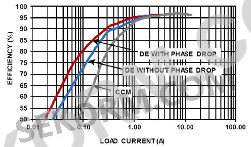
While DEM can improve efficiency under light loads, DEM can also pose some EMI challenges due to changing switching characteristics. To avoid EMI problems, it is often necessary to maintain continuous-on-mode (CCM) operation. However, as shown in Figure 1, we would be sacrificing the efficiency gains from diode simulation. However, in applications such as audio amplifiers, another way to achieve light-load efficiency improvements is to make the amplifier's power supply meet the requirements of tracking the input and have envelope tracking capability.
Forced PWM operation
Many power system applications require that the switching frequency of the converter be kept constant to reduce the possibility of interference. Due to this requirement, the ISL78227 and ISL78229 also operate in PWM mode (no pulse jumps). However, in forced PWM mode, when the reverse current may flow, such as when starting to a pre-biased output, or any time the output voltage is raised to a higher voltage than expected, these times are conditional. In a typical system, there is no way to limit the reverse current, which damages the synchronous FET. The ISL78227 and ISL78229 address this issue by including a reverse current limiting feature. Limiting negative current can reduce output voltage transients and improve system reliability. As a result, designers can configure a boost controller in forced PWM mode
Phase loss improves light-load efficiency
Phase loss improves light-load efficiency
The output voltage of the boost controller can be adjusted using an internal 1.6V reference voltage source, or it can be adjusted by an external tracking voltage to drive the control loop. The ISL78227 and ISL78229 controllers are unique in that the external signals used to drive the tracking function can be configured as analog voltage or PWM signals. These TRACK features support dynamically varying output boost voltages. It is useful for the controller to include negative current limiting and protection when the envelope tracking switches from a higher voltage to a lower voltage.
The output boost voltage should track the control signal, but when switching from a higher voltage to a lower voltage, the output capacitor must discharge to bring the voltage down. If the load itself is not consuming enough current, then synchronizing the FET can help discharge the output capacitance without worrying about FET damage due to overcurrent. This is because both controllers include negative current limiting and protection circuits for these types of conditions.
The ability to support envelope tracking without having to account for excessive reverse currents is particularly useful for audio applications where the supply voltage can vary rapidly over a wide range. In audio applications, the TRACK signal can be used to control the boost output voltage in order to track the signal amplitude of the audio amplifier as the signal changes. This smooths the power supply and prevents burrs when the load changes, thus preventing pops in the audio power amplifier.
Keep in mind that the power delivered to the speaker is a function of the amplifier's peak voltage output, as shown below:
Pavg=Vrms·Irms=V2rms/R=V2peak/2R
In automotive audio power amplifier applications, it is very common to boost a 12V battery to a higher voltage. The controller can boost the battery voltage up to 48V, or whatever voltage is needed to support the wattage of the audio power amplifier. Audio amplifiers typically have a power of 100-800 watts. Some advanced sound systems can install 30-40 watt amplifiers in multi-channel systems and use higher power amplifiers to drive heavy subwoofers.
In analog audio amplifiers, efficiency is improved if the supply voltage is only sufficient to support the audio signal. The efficiency benefits of a digital audio amplifier will depend on the digital amplifier architecture.
PMBus control
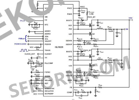
The ISL78229 boost controller, shown in Figure 3, includes a PMBus interface to help designers achieve ISO 26262 standards and Automotive Safety Integrity Level (ASIL). The PMBus interface is useful in systems that require real-time telemetry, fault reporting to microcontrollers, and system control. It provides ways to remotely enable or disable the boost controller, and monitor and report variables such as input voltage, input current, and output voltage. In addition, the boost controller includes a pin that supports the measurement of external negative temperature coefficient (NTC) resistance to monitor temperature, and then digitizes this signal so that readings can be reported via PMBus. Overtemperature fault limits can be set for external temperature monitoring.
In SUMMARY:
The ISL78227/29 Multiphase 55V synchronous Boost controller offers a combination of features to suit the requirements of many different power systems. Individually, these capabilities may seem insignificant, but when taken together, the whole is worth more than the sum of its parts. Voltage quality modules for start-stop systems, mainline audio amplifiers and in-glass window defrosters these are just a few of the high voltage applications in a powerful booster controller solution.
免责声明: 本文章转自其它平台,并不代表本站观点及立场。若有侵权或异议,请联系我们删除。谢谢! Disclaimer: This article is reproduced from other platforms and does not represent the views or positions of this website. If there is any infringement or objection, please contact us to delete it. thank you! |

WeChat Official Account

WeChat Service
 Email
Email QQ
QQ 13823761625
