Three phase full wave brushless motor excitation mode has 120 degree excitation drive and sine wave excitation drive two kinds. Compared with the 120-degree drive, the sine wave drive of the three-phase full wave brushless motor has more advantages in control accuracy, efficiency, noise, etc., but in terms of system complexity and cost, the rectangular wave drive of the three-phase full wave brushless motor is better.
Three phase full wave brushless motor drive: there are sensor, sine wave excitation PWM drive circuit example
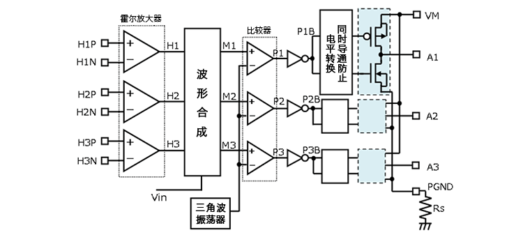
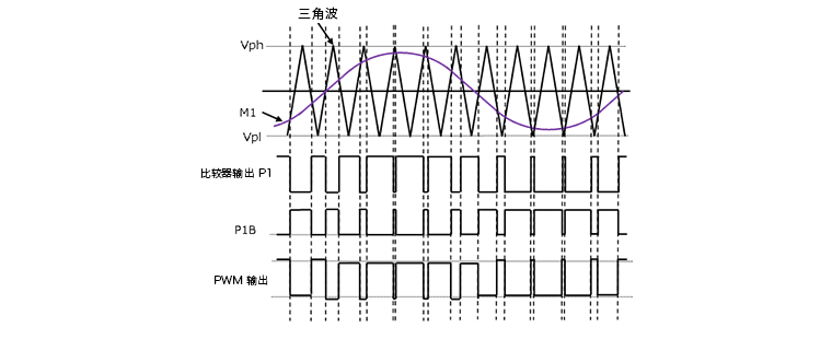
The sine wave drive is realized by the three-phase control and drive circuit of the driver composed of high side and low side switches. The following is an example of the circuit block diagram and each input and output waveform diagram of sinusoidal PWM driver with sensor. The basic work is to input the signal from the three Hall sensors to the input end of the Hall amplifier, and the signal synthesized by the waveform is converted into a PWM signal through the comparator and triangle wave, and the output MOSFET drives the coil of the motor. The equivalent voltage of A1, A2 and A3 PWM signals is a sinusoidal excitation waveform with a phase difference of 120 degrees. The 120-degree excitation is a rectangular wave excitation method with 120 degrees of conduction and 60 degrees of turn-off, but the sine wave drive is a 180-degree excitation, because it is through the sine wave to implement the excitation from zero to maximum, so the work is more stable and the noise is lower. In addition, PWM also helps to improve efficiency.

Three phase full wave brushless motor drive: there are sensor, sine wave excitation PWM drive waveform examples
The following uses examples of each waveform to explain in detail, first to understand the sine wave PWM conversion.

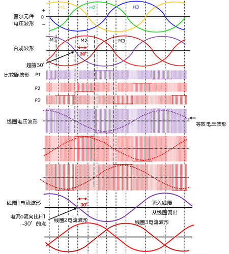
The input H1P/H1N ~ H3P/H3N of the Hall element voltage receives the signal from the Hall element in a differential manner and outputs a sine wave with a phase difference of 120 degrees from H1 to H3 (see the waveform diagram "Hall Element Voltage Waveform"). The Hall element voltage is formed into M1 ~ M3 by a waveform synthesis circuit. At this point, each waveform is generated with a phase more than 30 degrees ahead of the original phase (see "Resultant waveform"). The concept known as "lead Angle" will be described in more detail. As mentioned earlier, M1 ~ M3 is compared to a triangular wave by a comparator and converted into a PWM signal (see "Comparator waveform P1 ~ P3"). The voltage waveform of the motor coil is a PWM signal, but the waveform diagram shows the equivalent voltage waveform. It can be seen that the equivalent voltage waveform is driven by sine wave.

Of course, coil current is a sine wave. The phase Angle is advanced by the waveform synthesis circuit, so that the phase Angle of the coil current waveform is always 30 degrees ahead of the Hall element voltage (H1 ~ H3). This series of controls is called "lead Angle control". When the 120 degree excitation, there is a spike noise caused by the coil current ON/OFF in the coil voltage waveform, but when the sine wave excitation is driven, because it is 180 degree excitation, there is no ON/OFF, so there is no spike noise. The next article plans to introduce the related content of lead Angle control.
Key takeaways:
· The sine wave excitation PWM drive of the three-phase full wave brushless motor is a sine wave drive with a phase difference of 120 degrees.
· The sine wave excited PWM drive of the three-phase full wave brushless motor has an advantage in terms of noise because it does not produce spikes like the 120 degree excited drive of the three-phase full wave brushless motor.
· The sine wave drive of the three-phase full wave brushless motor achieves high efficiency through PWM drive.
免责声明: 本文章转自其它平台,并不代表本站观点及立场。若有侵权或异议,请联系我们删除。谢谢! Disclaimer: This article is reproduced from other platforms and does not represent the views or positions of this website. If there is any infringement or objection, please contact us to delete it. thank you! |


