
At present, wireless charging technology has begun to explore and apply in various fields. Because the farther the wireless transmission distance, the higher the energy consumption of the device. To realize long-distance high-power wireless electromagnetic conversion, the energy consumption of the equipment is high. Therefore, the realization of high-efficiency energy transmission of wireless charging is the primary problem for the popularity of wireless chargers. On the other hand, the problem to be solved is to establish a unified standard, so that different models of wireless chargers can match with different electronic products, so as to achieve wireless charging.
Wireless charging has gone from a dream to a reality, from a concept to a commercial product. Examples of wireless charging products:
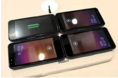
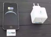
Picture: Mobile phone laptop wireless charger
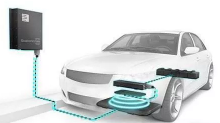
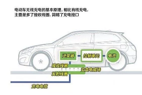
Figure: Wireless charging of new energy vehicles

Photo: Electric toothbrush wireless charging
Wireless power supply featuresAdvantages:
(1) Convenience: non-contact, one-to-many charging compared with the general charger, reduces the trouble of plugging, but also avoids the interface is not applicable, poor contact and other phenomena, the elderly can also be very convenient to use. A charger can charge multiple loads, and a family can buy a charger to meet the needs of the whole family.
(2) Versatility: A wide range of applications As long as the same wireless charging standard is used, no matter which manufacturer's device can be wireless charging.
(3) Novelty, good user experience
(4) With universal standards
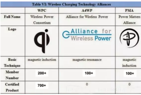
The mainstream wireless charging standards are: Qi standard, PMA standard, A4WP standard.
Qi standard: Qi standard is the world's first standardization organization to promote wireless charging technology - Wireless charging Alliance (WPC, established in 2008) launched the wireless charging standard, which uses the most mainstream electromagnetic induction technology, with compatibility and versatility of the two major characteristics. As long as it is a product with Qi logo, it can be charged with Qi wireless charger. In February 2017, Apple joined the WPC.
PMA Standards: The PMA Alliance is committed to creating wireless power standards for mobile phones and electronic devices that comply with IEEE Society standards, and has a leadership position in the field of wireless charging. PMA also uses the principle of electromagnetic induction to achieve wireless charging. Three companies, AT&T, Google and Starbucks, have joined the PMA alliance.
A4WP: The Alliance for Wireless Power Standard, launched in 2012, aims to establish a technical standard and industry dialogue mechanism for wireless charging devices for electronic products, including portable electronics and electric vehicles. A4WP uses the principle of electromagnetic resonance to realize wireless charging.
shortcoming
(1) Short working distance
Most of the current wireless charging technologies wirelessly charge electronic devices at near-magnetic fields within a short range. Because the farther the radio can be transmitted, the greater the power loss, the lower the energy transmission efficiency, and the higher the energy consumption of the equipment.
(2) The conversion efficiency is low and the speed is slow
Although the wireless charging technology is simple and convenient, its hard problem lies in the slow charging speed and charging efficiency.
(3) Higher power consumption, more power consumption
As the distance and power of wireless charging devices increase, the loss of idle work will be greater.
(4) The cost is high, the maintenance consumption is large, and there will be security risks if the standards are not met.
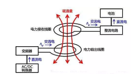
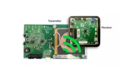
Wireless charging uses the principle of electromagnetic wave induction to charge, similar to the principle of transformers. There is a coil in the sending end and the receiving end. The sending end coil is connected to the wired power supply to generate an electromagnetic signal, and the receiving end coil senses the electromagnetic signal at the sending end to generate a current.
In June 2007, a research team led by Marin Soljacic at the Massachusetts Institute of Technology demonstrated for the first time the use of electromagnetic induction principle of light bulb wireless power supply technology, they can wirelessly provide power to 60 watts of light bulbs within a meter distance, power transmission efficiency of up to 75%.
The researchers thus hypothesized that the power supply could wirelessly charge the battery in this range, and deduced that only one power supply would be needed to power the entire house's electrical appliances. The transmission coil operates at a frequency in the megahertz range, and the receiving coil resonates within the non-radiating magnetic field, oscillating at the same frequency, and then efficiently transmits power through magnetic induction.

1, electromagnetic induction type
1890年,物理学家兼电气工程师尼古拉·特斯拉就已经做了无线输电试验,实现了交流发电。
迈克尔·法拉第发现电磁感应原理,电流通过线圈会产生磁场,其他未通电的线圈靠近磁场就会产生电流。
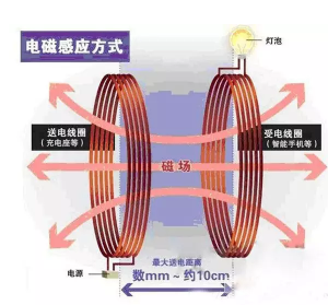
Electromagnetic induction is the most mature and common wireless charging technology at present, and the principle is somewhat similar to that of transformers.
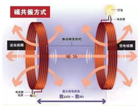
Compared with electromagnetic induction, resonance can extend the transmission distance. The magnetic resonance method is different from the electromagnetic induction method, and the position of the coils does not need to be completely matched.
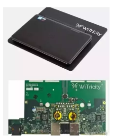
Application: ST collaborates with WiTricity to develop resonant radio energy transmission chips
ST and WiTricity, a pioneer in ultra-long range radio energy transmission technology, announced a collaboration to develop an electromagnetic resonant radio energy transmission semiconductor solution.
This solution supports fast wireless charging of consumer electronics and iot devices, and supports simultaneous charging of multiple devices. The electromagnetic resonance radio energy transfer chip is called "wireless charging 2.0", and unlike existing wireless charging technology, this chip can efficiently charge smartphones, tablets and smartwatches with metal shells.
3, radio wave type
Radio wave charging: This is a more mature technology, similar to the early use of ore radios, mainly composed of microwave transmitters and microwave receivers, can capture the radio wave energy bouncing off the wall, while adjusting with the load while maintaining a stable DC voltage. This method requires only a transmitter mounted in a wall plug and a "mosquito" receiver that can be installed in any low-voltage product.
The whole transmission system includes three parts: microwave source, transmitting antenna and receiving antenna. The microwave source has a magnetron, which can control the output power of the source in the 2.45 GHz band

AirVolt is a wireless charger that uses radio waves to charge mobile devices. As with similar products, it is less efficient than wired charging. After the AirVolt charging head is powered on, it can convert electrical energy into electromagnetic waves, and the receiver will convert electromagnetic waves into electrical energy to charge the phone. When the power is full to 80%, it will automatically stop charging, and when it is less than 20%, it will automatically charge, which ensures the best power of the phone and does not lead to overcharging, increasing the battery life.
The AirVolt, developed by TechNovator, can be charged remotely by plugging the receiver into the phone and plugging the charger into an outlet. The best charging distance is within 9 meters, and the longest distance can be up to 12 meters, hiding in any corner of the house can be charged! The receiver and charging head are small enough to charge more slowly than ordinary chargers. There are two types of Lightning or Micro usb interfaces to meet different needs.
4. Electric field coupling type
Electric field coupling charging principle: The use of the induced electric field generated by coupling two sets of asymmetric dipoles in a vertical direction to transmit power. The general charging module is composed of two asymmetric dipoles arranged in a vertical direction, which are composed of activated carbon electrodes and ground electrodes of the power supply part and the receiving part. The wireless power supply module is powered by the induced electric field generated by the electric field coupling of the two asymmetric dipoles.
The characteristics of electric field coupling are roughly three:
① Position freedom can be achieved when charging
② Thin electrode
③ The temperature of the electrode will not rise. This not only provides convenience, but also reduces system costs. At present, we have completed the trial production of the power supply station for portable terminals such as tablet terminals and e-books.
Analysis of existing solutions
Foreign companies that develop wireless charging technology (including chips/solutions/transmitting and receiving devices) mainly include IDT, TI, Freescale, Qualcomm, Broadcom, NXP, Fulton, Energous, Delphi, Panasonic, Toshiba, Fujitsu and so on.
In China, there are Zhonghui Chuangzhi, Xinpage, ZTE, Jingxin Micro, Mei Dada, Micro goose, Spouoting, China Resources Silico, Xinjie, Fuda, and Taiwan Lingyang.
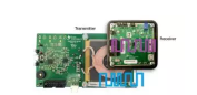
Different receivers are placed on the wireless charging transmitter, and the receivers can be different devices from small electric headphones to high-power laptop computers, so a mature solution should first be able to detect different targets; The power requirements of each receiving device will be different, and the transmitter needs to be able to automatically adjust the power output for power supply.
General wireless charging steps are divided into: detection, communication, power supply three stages.
(1) Detection phase: identification of power supply equipment and foreign matter (FOD)
When the receiver is placed within the transmitter operating range, the transmitter detects whether a receiver is near
(2) Communication phase: identity authentication
The transmitter sends the packet, and powers the receiver to start the receiver, after which the receiver replies the response data to complete the identity authentication
After identity authentication, the transmitter selects the corresponding power and other parameters according to the device type of the receiver to charge the receiver

Taking Qi standard as an example, the overall process is as follows:

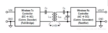
Today's wireless charging systems are designed in a resonant way, and the architecture is as large as the following structures: the transmitter has a DC power input, a frequency generation device, a switch to switch power, and a combination of transmitting coils and capacitive resonance; The receiver has a receiving coil and capacitor resonance combination and a rectifier; Filter and regulator; Dc power output.
1. IDT wireless IC solution
IDT's wireless charge and discharge IC achieves up to 87% wireless charge efficiency at 15W, improving the thermal performance of the system and comparable to traditional wired charging architectures. Its internal processor is based on the 32-bit ARM Cortex-M0 architecture, controlled via I2C communication, and provides an extended digital IO pin and associated software library.
Chip price ()P9242−RNDGI(15WTransmitter) 4.4
P9221-RAHGI8 (15W Receiver) 3.2P9038−RNDGI(5WTransmitter) 3.9
P9025AC-RNBGI (5W Receiver) $ 3.2
NXP MW series wireless charging IC solution
NXP offers solutions ranging from 5 W low power products to 15 W medium power products for the consumer electronics, industrial control and automotive electronics markets, including transmitter/receiver controller ics, associated software, evaluation boards and reference designs. The software contains all the resources needed to implement the core charging function, and also provides apis for customization and addition of functions.


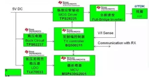
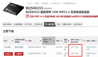
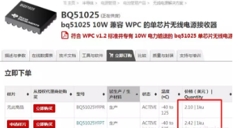
2. TI (BQ series) wireless charging scheme
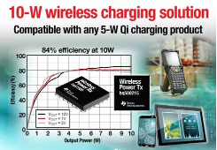
TI is the first mass-produced wireless charging solution company. Among them, in the 10W wireless charging solution, the output efficiency from the transmitter input to the receiver can reach 84%.
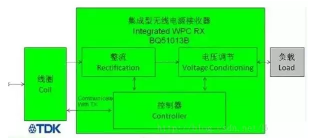
Receiver function block diagram:
In addition, TI introduced the third-generation radio receiver chips bq51020 and bq51021, and the world's first dual-model integrated circuit bq51221 to meet the WPC1.1 and PMA standards, these receiver solutions have reached 96% ultra-high efficiency. This completely eliminates the heat dissipation problem for full operation in smart phones and other portable devices under 5W conditions.
Cost evaluation reference:
Transmitter:
Receiver:
4. Toshiba Wireless IC solution
Toshiba Corporation's Storage and Electronic Component Solutions also announced that the wireless charging transmitter system using Toshiba's "TC7718FTG" 15W Wireless charging transmitter IC is certified to comply with the Qi v1.2 EPP(Extended Power Distribution) standard developed by the Wireless Charging Alliance (WPC). The system adopts MP-A2 (Wireless charging transmitter system using 12V single coil defined by the Wireless Charging Alliance) that supports simple system configuration, and MP-A2 transmitter system certified by Qi.
Toshiba introduces the wireless charging receiver IC, "TC7766WBG," which is certified to comply with the Qi v1.2 EPP(Extended Power Distribution) standard set by the Wireless Charging Alliance (WPC). The TC7766WBG is a QI-certified 15W receiver IC.
FAQ and related tests
1. Human harm:
When the electromagnetic wave frequency is increased to more than 1GHz, it will directly heat the water molecules. This principle becomes a microwave oven, so whether 13MHz will heat the metal or directly harm the human body above 1GHz, wireless power must solve the safety problem in the design before it can be listed
2, fever:
At the receiving end of the 5W demand, only 20% of the conversion efficiency, 20W of energy is converted into thermal energy dissipation, such energy will produce a huge heat energy, which will cause the system temperature to rise significantly, under this calculation, the maximum output capacity of the system will be 25W, if there is no safety design placed on the transmitter metal foreign matter may lead to fire accidents. Therefore, it is necessary to do device identification.
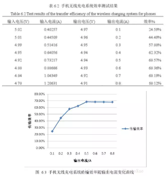
3, charge and discharge efficiency problem:
The input voltage of the transmitter is 5VDC, the distance between the receiving coils is 3cm, and the receiving end obtains electric energy through the receiving coil, and forms a stable 5v direct current through rectification and filtering.
4, mutual inductance influence: vertical distance and horizontal position influence
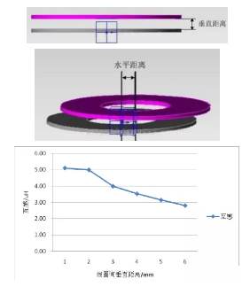
Inductive power transmission efficiency over long distances (separated by a certain space) is very low, while inductive power transmission near the device (such as the surface) can be really efficient, and its efficiency can be compared with wired transmission.
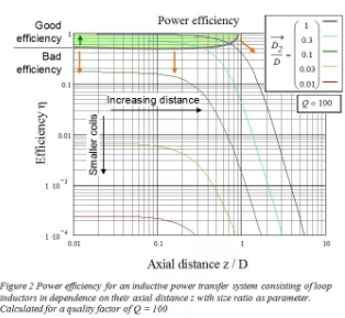
The greater the distance (z/D > 1) or the larger the gap in coil size, the greater the reduction in efficiency
The smaller the distance (z/D < 0.1), the closer the coil size is (D2/D = 0.5... 1), the higher the efficiency
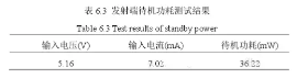
6. Power consumption problem
Under the same conditions as 2, the standby power consumption of the transmitter:
免责声明: 本文章转自其它平台,并不代表本站观点及立场。若有侵权或异议,请联系我们删除。谢谢! Disclaimer: This article is reproduced from other platforms and does not represent the views or positions of this website. If there is any infringement or objection, please contact us to delete it. thank you! |

WeChat Official Account

WeChat Service
 Email
Email QQ
QQ 13823761625
