The typical brushed DC motor is a very convenient but very noisy device. The brush reverses polarity, also known as "reversing," so that you only need to apply a constant DC voltage to turn the motor. But sudden connections and disconnections associated with these brushes cause transient interference that affects the circuits connected to the motor (via standard conduction paths) as well as nearby components (via EMI).
The obvious solution is to eliminate brushes, an approach that leads to brushless DC motors. The question is: how do you make a motor turn without a brush that provides continuous polarity reversal?
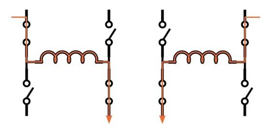
The general idea is to use electronic rather than mechanical devices for reversing. As you know, the motor is usually driven by a full-bridge circuit. They consist of four transistors arranged so that the current provided by the DC voltage source can be driven through the load in either direction. Therefore, even if the power supply of the driving circuit is always positive, we can reverse the polarity of the motor's magnetic field:

The difficulty here is that you need to know when to reverse polarity. The brushless DC motor automatically synchronizes internally, but if we use electronics instead of brushes, we need some kind of feedback about the rotor position. One way to get this feedback is through a Hall effect sensor.
Controller + Bridge + Hall
ROHM's BU69090NUX (which we'll call the 6909) is described as a single-phase motor driver for laptop cooling fans, though some creative readers can certainly find other (perhaps less mundane) applications.

The Hall element is actually inside the IC package. Therefore, you cannot use the 6909 to drive the motor on the other side of the room. When I look through the data sheet, I don't see any specific information about the necessary physical relationship between the IC and the motor.

The 6909 is a single-phase device because it has a full bridge for driving a single motor winding. This is in contrast to three-phase brushless DC motors, which have three windings and therefore require three drive circuits controlled by a well-designed commutation scheme.
Hall signal
Brushless DC motor control requires more than just Hall components. You can see in the block diagram that the Hall signal passes through the offset elimination block and is then digitized. Another feature not clearly shown in the figure is automatic gain control (AGC).
My understanding is that the amplitude of the feedback signal will vary depending on the characteristics of the motor and the distance between the motor and the chip, perhaps greatly. AGC has made the 6909 more versatile and user-friendly by ensuring that the 6909 can automatically compensate for these unpredictable changes. This rather complex diagram visually conveys AGC functionality:

Speed control
Adjusting motor speed is critical in many applications, so it's no surprise that the 6909 also includes this feature. Dc motors are usually driven by a fixed voltage source, so we cannot control the speed by changing the actual drive voltage. Instead, we change the average voltage delivered to the winding by modulating the output of the pulse width drive circuit.
The speed control of the 6909 is achieved through a PWM input pin, which (indirectly) controls the PWM duty cycle of the motor drive signal.

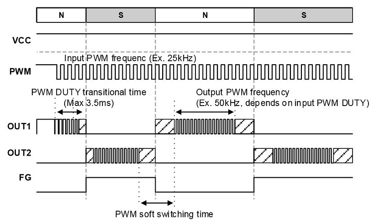
The PWM characteristics of the output signal are more complex than those of the input signal. The figure below illustrates in great detail how the 6909 actually works:

The polarity of the OUT1/OUT2 motor drive signal reverses as the detected magnetic polarity changes.
The FG output signal can be used to inform another component about the state of the motor.
The input PWM controls the output PWM, but not at the same frequency, and the output PWM changes before and after the conversion event (this is called the "soft switching" function).
免责声明: 本文章转自其它平台,并不代表本站观点及立场。若有侵权或异议,请联系我们删除。谢谢! Disclaimer: This article is reproduced from other platforms and does not represent the views or positions of this website. If there is any infringement or objection, please contact us to delete it. thank you! |


