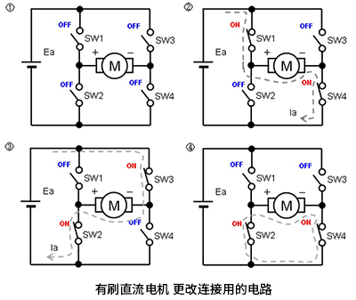
Brushed DC motors typically have two power connection terminals, through which voltage is applied to drive the motor. There are four basic connection methods for these two terminals:
Neither terminal is connected to any circuit. (If one end is connected but the other end is not, the situation is the same)
Connect the positive pole (+) of the DC power supply to one terminal and the negative pole (-) to the other terminal.
Connect the DC power supply to the motor with the opposite polarity to the second method.
Connect the two terminals directly.
These four states can be achieved by using a circuit composed of four switches, which is called an "H-bridge circuit" (also known as a "full bridge circuit") due to its structure resembling the letter "H".

Control method:
The H-bridge circuit can be controlled in various ways, including manual control, microprocessor control, or dedicated motor driver chips. The control signal must ensure that only one high side and one low side switch are closed simultaneously at any time to prevent short circuits, which is called "breakdown". To avoid this situation, a dead time is usually added between switches, which means that all switches are open for a period of time.
Matters needing attention:
When using H-bridge circuits, the following points should be noted:
Ensure that the control logic of the switch is correct to avoid breakdown
Select appropriate switching elements based on the current and voltage of the load.
Consider the issue of heat dissipation, as switches generate heat during operation.
If dealing with high-power loads, it may be necessary to use isolated drivers and protection circuits.
免责声明: 本文章转自其它平台,并不代表本站观点及立场。若有侵权或异议,请联系我们删除。谢谢! |


