
Products
Products
FM5012D
FM5012D is an integrated power management IC for mobile small fans, which integrates lithium battery charging management, three gear outputs, and status LED indication.
FM5012D is charged in a linear manner, integrating the entire charging process including trickle charging, constant current charging, and constant voltage charging. The float charging voltage accuracy can reach ± 1% over the entire temperature range, and it has the advantages of low charging current ripple and high charging efficiency.
FM5012D direct pulse square wave output drives the fan.
The FM5012D is equipped with two LED driver ports, and the button port can simultaneously drive the LED as a status indicator for the fan to turn on. In addition, the LEDR drives the LED indicator for the charging status.
FM5012DDescription:
FM5012D is an integrated power management IC for mobile small fans, which integrates lithium battery charging management, three gear outputs, and status LED indication.
FM5012D is charged in a linear manner, integrating the entire charging process including trickle charging, constant current charging, and constant voltage charging. The float charging voltage accuracy can reach ± 1% over the entire temperature range, and it has the advantages of low charging current ripple and high charging efficiency.
FM5012D direct pulse square wave output drives the fan.
The FM5012D is equipped with two LED driver ports, and the button port can simultaneously drive the LED as a status indicator for the fan to turn on. In addition, the LEDR drives the LED indicator for the charging status.
FM5012D has multiple protection designs, including load overcurrent protection, soft start protection, input overvoltage protection, output short circuit protection, chip temperature protection, etc. At the same time, the chip port is designed with a high-performance ESD protection circuit, making the chip highly reliable.
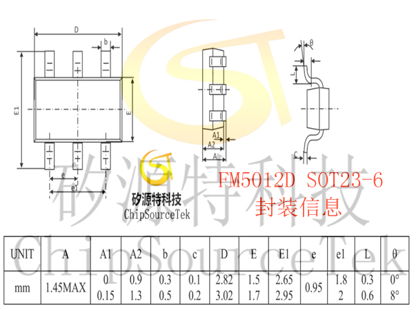
FM5012D currently offers SOT23-6 packaging form
FM5012D is charged in a linear manner, integrating the entire charging process including trickle charging, constant current charging, and constant voltage charging. The float charging voltage accuracy can reach ± 1% over the entire temperature range, and it has the advantages of low charging current ripple and high charging efficiency.
FM5012D direct pulse square wave output drives the fan.
The FM5012D is equipped with two LED driver ports, and the button port can simultaneously drive the LED as a status indicator for the fan to turn on. In addition, the LEDR drives the LED indicator for the charging status.
FM5012D has multiple protection designs, including load overcurrent protection, soft start protection, input overvoltage protection, output short circuit protection, chip temperature protection, etc. At the same time, the chip port is designed with a high-performance ESD protection circuit, making the chip highly reliable.
FM5012D currently offers SOT23-6 packaging form
The peripheral circuit is simple and does not require an external MOS
Low standby current 7uA
Programmable full charge voltage, charging float voltage accuracy ± 1%
Soft start function
Trickle current/constant current/constant voltage three-stage charging
FAN output overcurrent, short circuit, overvoltage protection
Display mode of 2-light status
Packaging form: SOT23-6
FM5012Dapplication:
Mobile small fan
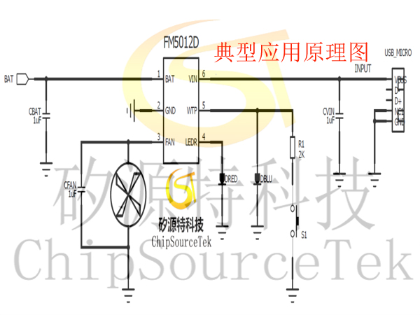
FM5012DTypical application circuit:
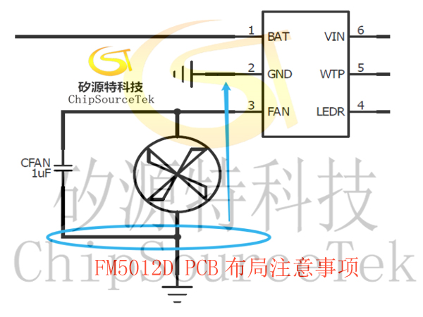
1. GND
The FAN and GND pins of the chip are respectively the power supply and ground of the chip driving part. During the operation of the switch, there will be instantaneous large currents flowing in and out. Therefore, when drawing the PCB, the negative terminal of CBAT should be as close as possible to PIN2.GND and should not be through holes. The negative terminals of CFAN and fan should be arranged as close as possible to PIN2.GND to prevent interference on the ground wire from affecting the operation of the chip.
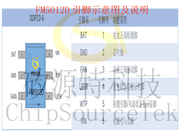
FM5012DPin diagram and explanation:
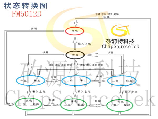
FM5012Dstate transition diagram:
FM5012DFunction Description:
Charging management
1. Charging mode
FM5012D uses a linear method for three-stage charging of batteries, including trickle/constant current/constant voltage charging. Perform trickle charging when the battery voltage is below V TRKL; Perform constant current charging when the battery voltage is higher than V TRKL; When the battery voltage approaches V BAT-REG, constant voltage charging is performed, and the charging current gradually decreases. When the current decreases to I FULL, it is judged that the battery is fully charged, and the chip terminates charging. Recharge is performed after the battery voltage drops to V RECHG.
2. Charging soft start function
When starting to charge the battery, the chip controls the charging current to gradually increase to the set value, avoiding various problems caused by sudden high current surges.
3. Charging current setting
The charging current is set to a constant current of 600 mA by the internal circuit, 60mA for trickle charging, and 90 mA for I FULL. The programmable charging saturation voltage is set to 500 mA, 50mA for trickle charging, and 75 mA for I FULL. When the input power supply is insufficient or the chip temperature is too high, the I IN-LIM will decrease.
4. Full charge voltage setting
The default full charge voltage value of FM5012D chip is 4.20V, and the programmable set full charge voltage value is 4.35V
5. Input overvoltage protection
When the input voltage exceeds V IN-OVP, the chip will control the shutdown of charging and boost output to prevent damage to the chip and load due to overvoltage. After the input voltage returns to normal, charging will resume, but the fan drive output FAN will not recover.
6. Charging current limiting protection
When the voltage at the VIN port of the chip is lower than 4.7V, the chip enters the VIN current limiting state, and the charging current gradually decreases until it reaches zero.
FM5012DOutput driven fan function:
FM5012D Charging and discharging function at the same time:
FM5012D LED Display mode:
Lamp socket connection: FM5012D defaults to two status indicator lights.
The charging status indicator light is connected to the LEDR port, which is connected to the positive terminal of the LED, and the negative terminal of the LED is connected to GND;
There are two ways to connect the fan working status indicator light:
1) The positive terminal of the fan working status LED is connected to the WTP pin (default connection method)
2) The positive terminal of the fan working status LED is connected to FAN through a resistor, and the negative terminal of the LED is connected to GND (programmable selection)
Attention: When the fan status light is connected to the FAN port and there is no VIN inserted, and the battery level is low, the fan status light still stays on, but the charging status light shows a square wave with a 0.5S cycle
FM5012D Other functions:
1. Key Control Function (WTP)
Short press and long press buttons have the same function, which is to activate the discharge switch;
The WTP port needs to be connected in series with a 2k resistor to the button end, and the other end of the button to GND
Short press and long press buttons have the same function, which is to activate the discharge switch;
The WTP port needs to be connected in series with a 2k resistor to the button end, and the other end of the button to GND
FM5012D Application Description:
1. Selection of capacitors:
CBAT and CFAN can use ceramic capacitors, and the recommended voltage withstand is 10V. Increasing CBAT and CFAN will make the system more stable. In any case, choosing capacitors with poor quality may cause a decrease in overall system performance, shortened service life, or even malfunction, so please choose capacitors carefully.
CBAT and CFAN can use ceramic capacitors, and the recommended voltage withstand is 10V. Increasing CBAT and CFAN will make the system more stable. In any case, choosing capacitors with poor quality may cause a decrease in overall system performance, shortened service life, or even malfunction, so please choose capacitors carefully.

Please submit your basic information, send an email to Sales@ChipSourceTek.com, or call us at 13823761625 (same number as WeChat), and we will contact you as soon as possible!

WeChat Official Account

WeChat Service
 Email
Email QQ
QQ 13823761625
