
Products


CST6307
The CST6307 can enter low-power sleep mode when the system does not require a drive motor.
The CST6307 provides an internal shutdown function for UVLO and overheat protection.
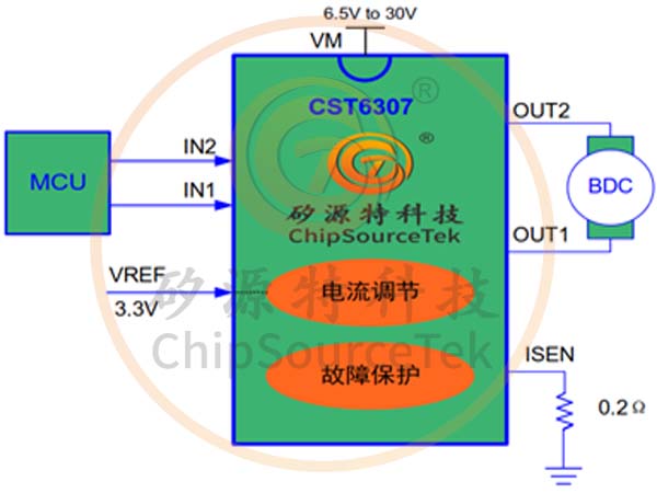
The CST6307 is a motor drive for brushed DC that can operate from 6.5V to 25V, providing up to 3.6A peak current. The CST6307 integrates a current modulation circuit to set the operating current according to the VREF and the resistance external to the ISEN. A simple PWM interface can realize the connection and control of the controller.
The CST6307 can enter low-power sleep mode when the system does not require a drive motor.
The CST6307 provides an internal shutdown function for UVLO and overheat protection.
The CST6307 is a brushed DC motor driver for high-current toys, robots, printers, POS machines, appliances and other small machines. Two logical inputs control the H-bridge driver, which consists of four n-channel metal-oxide-semiconductor field-effect tubes (MOSFETs), capable of bidirectional control of the motor at peak currents up to 3.6A. Using the current attenuation mode, the motor speed can be controlled by pulse width modulation (PWM) of the input. If these two inputs are set to low, the motor driver will enter low-power sleep mode.
The CST6307 features integrated current regulation based on the analog input VREF as well as the voltage of the ISEN pin (proportional to the motor current flowing through the external sensing resistance). The device is able to limit current to a certain level value, which can significantly reduce system power requirements, and does not require large capacity capacitors to maintain a stable voltage, especially when the motor is started and stopped.
The CST6307 integrates various protection functions to achieve internal shutdown function in case of failure, providing undervoltage locking and overheat protection. In addition, a low-power sleep mode is provided.
The CST6307 is available in an e-SOP8 package with heat sink.
CST6307 Features:
Single channel H-bridge motor driver with current control
Single channel H-bridge motor driver with current control
Drive a DC motor, a stepper motor winding, or other load
Operating voltage range: 6.5V-25V
Low on-resistance: high side + low side (HS+LS=560 mω)
3.6A peak current drive capability
Pulse width modulation (PWM) control interface
Integrated protection feature
- VM Undervoltage Block (UVLO)
- Thermal shutoff (TSD)
Automatic fault recovery
Integrated current regulation
Low power sleep mode
Available in an e-SOP8 package with heat sink.
CST6307 Applications:
High current toys, robots, printers, POS machines, other mechatronics applications, etc
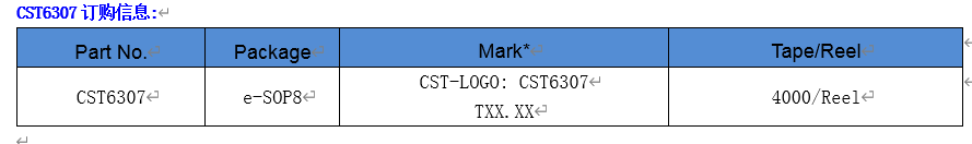
CST6307 Ordering Information:
CST6307 Application circuit:

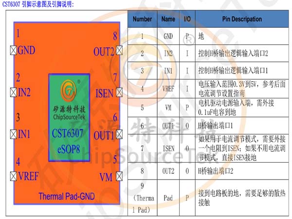
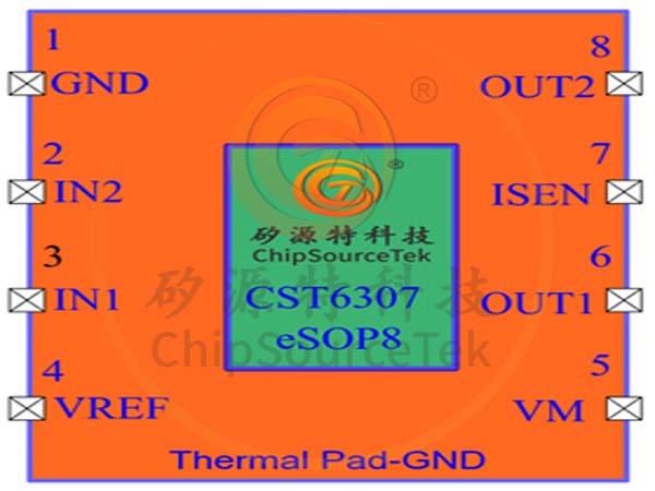
CST6307 pin diagram and pin description:


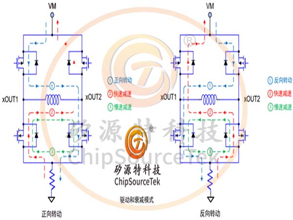
CST6307 Bridge control and attenuation modes
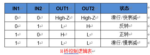
The output pin AOUTx and BOUTx status is controlled by the input pin AINx and BINx. The following diagram (H-bridge control logic table) lists the input corresponding output status description:
The CST6307 uses PWM mode to control the motor speed regulation function through input-input-IN2 logic signals. When the MOSFETs on the high side are turned on, the induced current in the motor winding will continue to rise, and if the MOSFETs on the high side are turned off, the induced current in the winding will produce a continuous current. In order to reasonably handle the current of the motor coil, the H-bridge has two different working state modes, fast attenuation and slow attenuation, in the fast attenuation mode, the internal H-bridge of the CST6307 is turned off, and the continuous current flows to the body diode, in the slow attenuation mode, the current of the motor will cycle between the two low-side MOSFETs.
In the fast attenuation mode, when the PWM modulation signal is input from outside, the PWM signal is IN1 input on one side, and the other side is low; In slow attenuation mode, one side of the IN2 input, the other side needs to be high, as shown in the table (PWM control motor drive logic table).
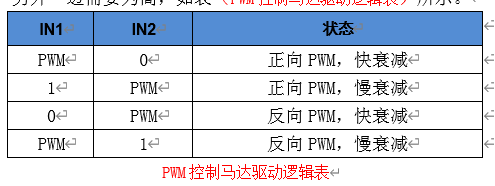
When the PWM is fed to IN1, the internal current control is still on and can be turned off when the ISEN pin is connected directly to GND. The figure (drive and attenuation modes) illustrates the attenuation mode of the current under different drives.

CST6307 Current control
The CST6307 limits the current value by simulating the resistance of the input pin VREF and the external ISEN according to the following formula:
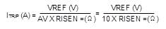
For example, if VREF=3.3V and RISEN=0.15Ω, the CST6307 limits the motor drive current to 2.2A regardless of the load.
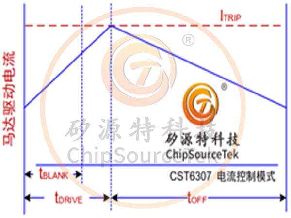
When the ITRIP level is reached, the device forces current attenuation by opening the two FETs on the bottom edge, and will turn off the tOFF (typical value 25uS).

Once tOFF time is up, the input is re-enabled, working according to the state of the two inputs. Drive time The time when tDRVIE reaches ITRIP is related to VM voltage, drive inductance and other factors.
CST6307 nSLEEP Sleep mode control
When IN1 and IN2 are both low sustained tSLEEP (typical value 1mS), the CST6307 will enter low power mode, and when IN1 or IN2 is at least 5uS high, the device will enter operation after tON (typical value 50uS).
CST6307 protection circuit The CST6307 includes over current protection (OCP), over temperature protection (TSD) and under voltage protection UVLO.
Overcurrent Protection (OCP) Both high-side and low-side MOSFETs independently detect overcurrent, which means that a short circuit to the ground, a short circuit to the power supply, or a short circuit at both ends of the motor winding will cause the overcurrent to turn off. Overcurrent protection does not use the current detection circuit used for PWM current control, so it works even without an ISEN resistor.
Overtemperature Protection (TSD) If the chip temperature exceeds the safety threshold, all MOSFETs in the H-bridge will be disabled, and operation will resume automatically once the temperature recovers and drops to the safety setting level.
Undervoltage Protection (ULVO) Such as drive and attenuation mode table. If the VM voltage falls below the undervoltage lock threshold voltage at any time, the chip is disabled and all internal logic is reset. When the VM rises above UVLO, the operation resumes.
CST6307 Power Supply Selection Guide
In the design of motor drive system, proper large-capacity capacitance configuration is an important factor. Generally, the larger the capacitance, the more conducive to the safety and stability of the system, while the disadvantage is the increase in cost and physical size. The value of capacitance is determined by a variety of factors, including:
The maximum current required by the motor system
The ability of a capacitor to provide current
The amount of parasitic inductance between the power supply and the motor system
Acceptable voltage ripple
Type of motor used (brushed, brushless and stepper)
Motor braking mode
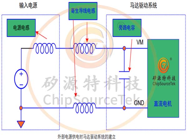
As shown in the figure, the inductance between the power supply and the motor drive system limits the rate at which current can be obtained from the power supply. If the local large-capacity capacitance is too small, the system will result in a decrease in voltage when it responds to too fast and excessive current changes. When a sufficiently large capacitor is used, the motor voltage can remain stable, thus providing a high current quickly. The data sheet usually provides a recommended value, but a full system-level test is required to determine the appropriate capacitance.
The rated voltage of large capacity capacitors should be higher than the operating voltage, leaving a certain margin to prevent the occurrence of the motor to transfer energy to the power supply in turn, so as to avoid damage.

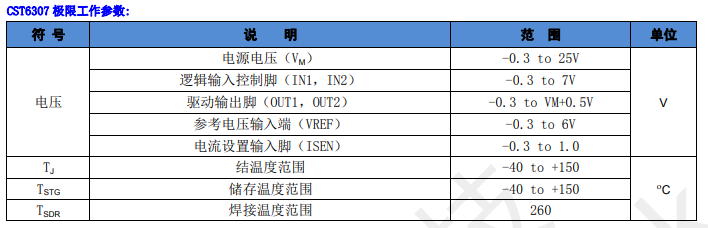
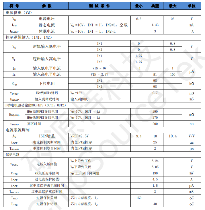
CST6307 root operating parameters:
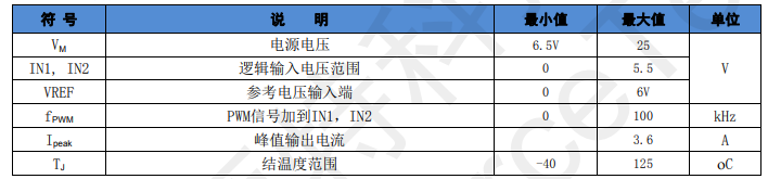
CST6307 Working Conditions:
CST6307 functional block diagram:

CST6307 Esop8 Package Information:


Please submit your basic information, send an email to Sales@ChipSourceTek.com, or call us at 13823761625 (same number as WeChat), and we will contact you as soon as possible!

WeChat Official Account

WeChat Service
 Email
Email QQ
QQ 13823761625
