
Products
Products
MX08
The product adopts H-bridge circuit structure design, adopts high reliability power tube technology, especially suitable for driving coil, motor and other inductive loads. N-channel and P-channel power MOSFETs are integrated into the circuit, and the operating voltage range covers 2V to 9.6V. At 27℃, the maximum continuous output current reaches 1A and the maximum peak output current reaches 1.5A when VDD=6.5V.
MX08 Description:
The product adopts H-bridge circuit structure design, adopts high reliability power tube technology, especially suitable for driving coil, motor and other inductive loads. N-channel and P-channel power MOSFETs are integrated into the circuit, and the operating voltage range covers 2V to 9.6V. At 27℃, the maximum continuous output current reaches 1A and the maximum peak output current reaches 1.5A when VDD=6.5V.
The single circuit is a power device with a certain internal resistance. The heating of the circuit is closely related to the load current, the internal resistance of the power tube and the ambient temperature. The circuit is designed with a chip-level temperature detection circuit to monitor the internal heat of the chip in real time. When the internal temperature of the chip exceeds the set value (typical value 150 ° C), the power tube will be turned off and the load current will be turned off to avoid the continuous rise in temperature caused by abnormal use, which will cause serious safety accidents such as smoke and fire in plastic packaging. The built-in temperature hysteresis circuit of the chip ensures that the circuit returns to the safe temperature before allowing the power tube to be controlled again.
MX08 Features:
Low standby current (less than 0.1uA)
Low on-internal resistance MOSFET power switch tube
- MOS technology is used to design the power tube
- 800 mA channel power tube internal resistance 0.6 ohms
- 200 mA channel power tube internal resistance 0.55 ohms
VCC can be suspended under certain conditions
- The minimum high level voltage of the input signal is greater than 2.4V
Small input current
- Integrate about 15K against underground pull resistance
- The VCC is properly connected and the average input current of the 3V drive signal is 200uA
- VCC suspended, 3V drive signal average 350uA input current
Built-in overheating Protection circuit with hysteresis (TSD)
Antistatic grade: 3KV (HBM)
MX08 Applications:
2-6 AA/AAA dry battery powered toy motor drive
2-6 nickel-hydrogen/nickel-cadmium rechargeable batteries are powered by toy motors
1-2 lithium battery powered motor drive
Electronic lock
2-6 nickel-hydrogen/nickel-cadmium rechargeable batteries are powered by toy motors
1-2 lithium battery powered motor drive
Electronic lock
MX08 Ordering Information:
Product model | Package | Operating temperature |
MX08 | SOP8 | -20℃ ~ 85℃ |
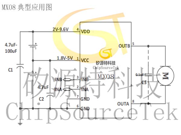
MX08 Typical application diagram:
MX08 pin arrangement:
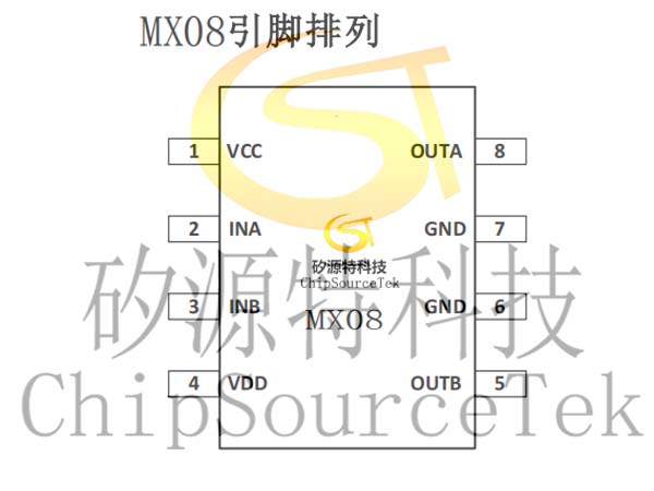
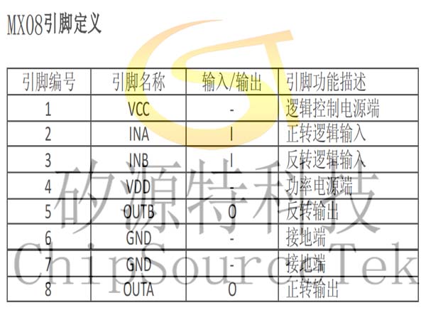
MX08 pin definition:
MX08 functional block diagram:

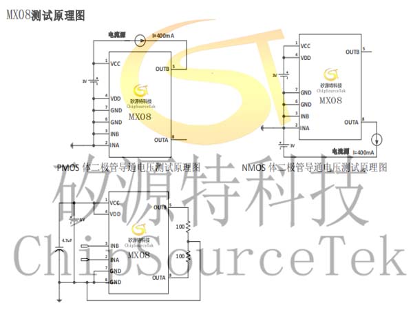
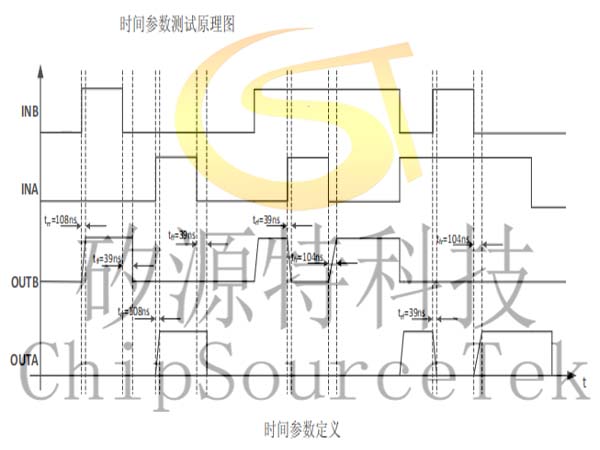
MX08 test schematic diagram:
MX08 motor drive typical application circuit diagram:

Special note:
Capacitor C1 in Figure 1 is the decoupling capacitor between the power supply and the ground. The capacity value of capacitor C1 can be selected according to different application conditions. The specific provisions are as follows:
A. When the VDD voltage is less than 7.2V(4 new dry batteries) and the peak current does not exceed 1.5A, the capacitor C1 can be eliminated.
B. Under the application conditions of VDD voltage 7.2V-9.6V and peak current exceeding 1.5A, capacitor C1 can not be eliminated, and the value of capacitor C1 should be selected between 47uF-100uF according to the actual motor situation.
C, the type of capacitor C1 is not limited, can be porcelain capacitor or electrolytic capacitor.
Logic power supply VCC ground capacitor C2 must require at least 4.7uF, practical applications do not need to be close to the chip to add a separate capacitor, can be shared with other control chips (RX2, MCU) and so on. If the VCC does not have any capacitance to the ground, the circuit may enter a locked state when the circuit enters overheat protection mode due to overload. After entering the locked state, the state of the input signal must be changed once again to restore the circuit to normal. As long as the VCC has more than 4.7uF capacitance to the ground, the circuit will not appear locked.
The 0.1uF capacitor (C3) between the drive circuit OUTA and OUTB in Figure 1 is the capacitor connected to both ends of the motor and does not need to be added
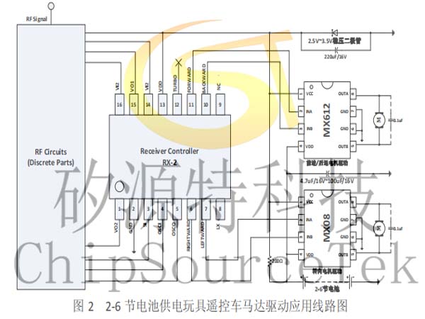
The motor drive application circuit diagram shown in Figure 2, where the steering wheel drive current is small, MX08 can be selected as the drive circuit. The rear wheel motor drive current is large, can choose our other products according to specific requirements, such as MX612, MX618.
The VDD to ground decoupling capacitor in Figure 2 should be selected according to the actual usage. The higher the VDD voltage, the larger the motor current and the larger the capacitance value. The capacitance value depends on the actual use of the motor, and it is recommended that the value of the capacitor C1 be between 4.7uF-100uF.
The 0.1uF capacitor between the drive circuit OUTA and OUTB in Figure 2 is the capacitor connected to both ends of the motor and does not need to be added separately.
VCC and VDD must be wired separately, VCC only accepts static voltage within 5V, must be a common power supply with the main control chip, otherwise the motor switching generated by the electromotive force may breakdown the logic part, even if the VDD voltage within 5V also need to be wired separately.
MX08 electronic lock typical application circuit diagram:

When the MX08 is used to drive the electronic lock switch, the logic power supply VCC is suspended, but the input input high voltage is required to exceed 2.4V. Capacitor C1 in Figure 3 is the decoupling capacitor between the power supply VDD and the ground, and the value of capacitor C1 can be 4.7uF in application.
The 0.1uF capacitor (C2) between the drive circuit OUTA and OUTB in Figure 3 is the capacitor connected to both ends of the electronic lock motor and does not need to be added separately.

Please submit your basic information, send an email to Sales@ChipSourceTek.com, or call us at 13823761625 (same number as WeChat), and we will contact you as soon as possible!

WeChat Official Account

WeChat Service
 Email
Email QQ
QQ 13823761625
