
Products
Products


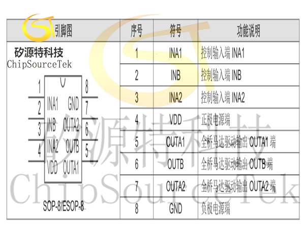
TC1305EA,TC1305E.
TC1305EA,TC1305E. Typical is a single-channel low-on-resistance DC motor drive integrated circuit designed for systems operating at low voltage.
The integrated motor forward/reverse/stop/brake four features built-in temperature protection function, when the 5EA, the 5E. When the temperature exceeds the maximum temperature set by the internal temperature protection circuit, the internal circuit turns off the built-in power switch tube and cuts off the load current to avoid safety hazards such as smoke and fire caused by excessive temperature.
The integrated motor forward/reverse/stop/brake four features built-in temperature protection function, when the 5EA, the 5E. When the temperature exceeds the maximum temperature set by the internal temperature protection circuit, the internal circuit turns off the built-in power switch tube and cuts off the load current to avoid safety hazards such as smoke and fire caused by excessive temperature.
TC1305EA,TC1305E. Description:
TC1305EA,TC1305E. Typical is a single-channel low-on-resistance DC motor drive integrated circuit designed for systems operating at low voltage.
TC1305EA,TC1305E. Typical is a single-channel low-on-resistance DC motor drive integrated circuit designed for systems operating at low voltage.
Tc1303as, 5E. Available in SOP8 and ESOP8 packages
Single channel built-in power MOS full bridge drive
Forward, reverse and stop functions
Built-in hysteretic heat effect overcurrent protection function
Continuous output current up to 2.7A(ESOP-8), peak current 5.5A
TC1305EA, 5E. In SOP8 and ESOP-8 encapsulation form
Forward, reverse and stop functions
Built-in hysteretic heat effect overcurrent protection function
Continuous output current up to 2.7A(ESOP-8), peak current 5.5A
TC1305EA, 5E. In SOP8 and ESOP-8 encapsulation form
Toy DC brush
Brushless motor drive and other products
Tc1303ea, 5E. Ordering Information:
Brushless motor drive and other products
Tc1303ea, 5E. Ordering Information:
| Product model | Encapsulation form |
| TC1305 | SOP-8 |
| TC1305EA | ESOP-8 |
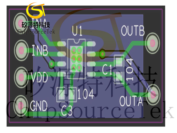
Note: In different applications, C2, C3 can be considered to install only one: in 3V applications, it is recommended to use a 1uF or above; A 4.7uF or above is recommended for 4.5V applications; A 10uF or above is recommended for 6V applications; It is recommended to use 22uF or above in 7.2V applications, where the chip capacitor is placed near the VDD pin of the IC and the connection between the negative terminal of the capacitor and the GND terminal of the IC should be as short as possible as shown below. That is, although the capacitor is close, the wiring and wiring are wound very far. In addition, when using a large electrolytic plug-in capacitor, it is recommended to follow the above rules and a 100nF. When there is a large capacitor on the application board to filter other chips and it is far away from the C1305EA, a small capacitor should be placed on the VDD foot of the 5EA as required above. If C1 in the figure cannot be welded to the motor, it is designed on the PCB.
Tc1303as, 5E. Note to use:
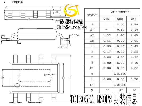
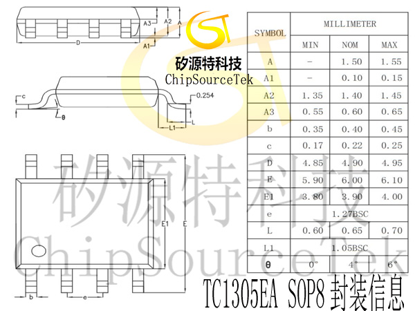
Tc1303ea, 5E. Package Size Diagram:
SOP8:
TC1305EA,TC1305E.封装尺寸图:
MSOP8:

Tc1303as, 5E. Note to use:
1, the above recommended circuit and parameters are only applicable to ordinary toy products, other please use according to the actual situation.
2, continuous current drive ability is affected by packaging form, ambient temperature, PCB material size thickness and other factors, specifications given parameters for reference only. In actual use, please consider a certain margin according to the product. That is, if the heat dissipation conditions are good, the sustainable current will be large, and on the contrary, it will soon enter the overheating protection.
3. The MOS process was used to design and manufacture, which was sensitive to static electricity and required anti-static measures in the whole process of packaging, transportation, processing and production.
4. The current value of the motor starting moment is recommended not to exceed 5A.
Tc1303ea, 5E. Package Size Diagram:
SOP8:
TC1305EA,TC1305E.封装尺寸图:
MSOP8:

Please submit your basic information, send an email to Sales@ChipSourceTek.com, or call us at 13823761625 (same number as WeChat), and we will contact you as soon as possible!

WeChat Official Account

WeChat Service
 Email
Email QQ
QQ 13823761625
