
Products
Products
FM1668
FM1668 is a special circuit for LED (light emitting diode display) driver control with keyboard scanning interface, which is integrated with MCU digital interface, data latch, LED high voltage driver, keyboard scanning and other circuits. This product has excellent performance and reliable quality. Mainly used in VCR, VCD, DVD and home theater and other products display driver.
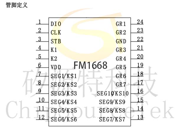
The FM1668 is packaged in the SOP-24 format.
The FM1668 is packaged in the SOP-24 format.
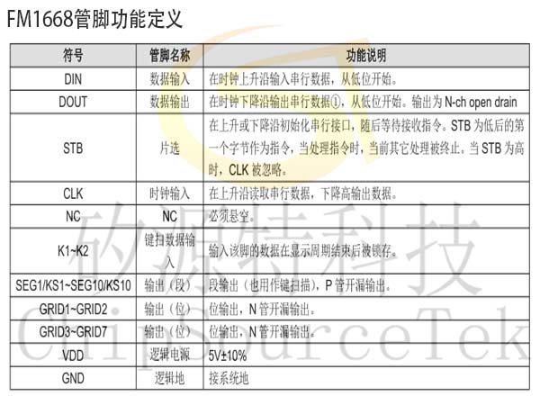
FM1668 Description:
Power CMOS technology is adopted
Display mode (10 segments x 7 bits)
Key scan (10×2bit)
Brightness adjustment circuit (duty cycle 8 adjustable)
Serial interface (CLK, STB, DIN, DOUT)
Oscillation mode: Built-in RC oscillation (450KHz±5%)
Built-in power-on reset circuit
Package format: SOP-24
Display mode (10 segments x 7 bits)
Key scan (10×2bit)
Brightness adjustment circuit (duty cycle 8 adjustable)
Serial interface (CLK, STB, DIN, DOUT)
Oscillation mode: Built-in RC oscillation (450KHz±5%)
Built-in power-on reset circuit
Package format: SOP-24
Note:
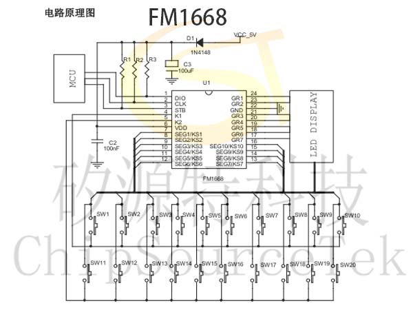
1. When it is recommended to use, the I2C bus port external on-resistor as shown in the figure R1-R3 is recommended to use 2.2K-10K according to the MCU used;
2, in order to reduce the crosstalk of the system signal, it is recommended that the MCU of the product be isolated from the positive electrode of the FM1668 power supply series 1N4148 diode, if the program interference is not large and there is no adverse phenomenon such as logic confusion, the diode is not needed.3, PCB wiring, as shown in the figure above, C2 should be placed close to the chip VDD foot and its connection should be as short as possible, C2's negative extreme (ground) should also be as short as possible with the chip's 22nd foot connection, if the ground around the far to the 22nd foot, then C2 decoupling effect on FM1668 is almost invalid.

Please submit your basic information, send an email to Sales@ChipSourceTek.com, or call us at 13823761625 (same number as WeChat), and we will contact you as soon as possible!

WeChat Official Account

WeChat Service
 Email
Email QQ
QQ 13823761625
