
Products
Products

IP5568
IP5568 is a power management SOC that integrates wireless charging TX/RX, QC2.0/QC3.0/SCP/VOC output fast charging protocol, FCP/AFC/SFCP input/output fast charging protocol, MTK PE+1.1&2.0 output fast charging protocol, USB C/PD2.0/PD3.0 input/output protocol, USB C PD3.0 PPS output protocol, compatibility with BC1.2/Apple/Samsung phones, synchronous up/down converter, lithium battery charging management, battery level indicator and other functions, providing a complete power solution for fast charging mobile power banks.
IP5568 Description:
IP5568 is a power management SOC that integrates wireless charging TX/RX, QC2.0/QC3.0/SCP/VOC output fast charging protocol, FCP/AFC/SFCP input/output fast charging protocol, MTK PE+1.1&2.0 output fast charging protocol, USB C/PD2.0/PD3.0 input/output protocol, USB C PD3.0 PPS output protocol, compatibility with BC1.2/Apple/Samsung phones, synchronous up/down converter, lithium battery charging management, battery level indicator and other functions, providing a complete power solution for fast charging mobile power banks. It can simultaneously support four USB ports: USB A x2, USB B, and USB C. Using any one USB port alone can support fast charging. When using two or more output ports simultaneously, it only supports 5V. IP5568 supports both wireless charging and USB port usage simultaneously.
The high integration and rich functions of IP5568 only require one inductor to achieve voltage reduction and boost functions, which requires very few peripheral devices in application, effectively reducing the size of the overall solution and lowering BOM costs.
The synchronous switch boost system of IP5568 can provide a maximum output capacity of 22.5W, and can maintain an efficiency of over 90% even when the battery voltage is low. Automatically enter sleep mode when unloaded.
The IP5568 synchronous switch charging system provides up to 5.0A charging current. Built in IC temperature, battery temperature, and input voltage control loop, intelligently adjusting charging current.
IP5568 has built-in USB C&PD2.0/PD3.0 protocols.
IP5568 has a built-in 14 bit ADC for precise measurement of battery voltage and current. IP5568 has a built-in battery level calculation method that can accurately obtain battery level information. Customizable battery level curve to accurately display battery level.
IP5568 supports 1/2/4 LED battery display, and supports various digital tube battery displays such as 88 and 188; Support lighting function; Support buttons.
IP5568 Features:
*Simultaneously supporting multiple USB ports and wireless charging
- 2 USB A ports for output, 1 USB B port for input
- 1 USB C-port input/output, 1 wireless charging TX/RX
*5W/10W/15W wireless charging transmitting and receiving unit
- Compatible with WPC v1.2.4 protocol, supporting 5w/7.5w/10w/15w wireless charging and transmitting specifications
- Support wireless charging 5w/10w receiving specifications
- Integrated MOS full bridge driver, integrated internal voltage/current demodulation
- Support FOD foreign object detection function
- Supports wireless transmission, wired output or input working simultaneously
- Supports single coil, double coil, and triple coil
*Fast charging specifications
- Either port supports fast charging
- Integrated QC2.0/QC3.0 output fast charging protocol
- Integrated FCP input/output fast charging protocol
- Integrated AFC input/output fast charging protocol
- Integrated SFCP input/output fast charging protocol
- Integrated SCP output fast charging protocol
- Integrated VOOC output fast charging protocol
- Integrated MTK PE+1.1&2.0 output fast charging protocol
- Integrated USB C DRP protocol, supports input/output fast charging
- Can support customization of 20W PDO
PDO:5V 2.4A、9V 2.22A、12V 1.67A
PPS 3.3V~11V 2A
- Compatible with BC1.2, Apple, Samsung phone fast charging
*Integrated USB Power Delivery (PD2.0/PD3.0) protocol
- Support PD2.0 bidirectional input/output protocol
- Supports PD3.0 input/output and PPS output protocol
- Supports 5V, 9V, 12V voltage range input and output
- PPS supports 5~11V, 20mV/step output voltage levels
- Bidirectional Label Encoding and Decoding (BMC) Protocol with Integrated Hardware
- Integrated Physical Layer Protocol (PHY)
- Integrated hardware CRC, supporting Hard Reset
*Charging specifications
- The maximum charging current at the battery end can reach 5.0A
- Adaptive charging current regulation
- Supports 4.20V, 4.3V, 4.35V, 4.40V batteries
*Discharge specifications
- Output current capability: 5V: 3.1A 9V: 2.0A 12V: 1.5A
- Customizable support for 20W output current capability
9V 2.22A 12V1.67A
- Synchronous switch discharge 5V 2A efficiency reaches over 95%
- Support line supplementation
*Battery level display
- Built in 14 bit ADC and battery meter
- Support 1/2/4 LED power display
- Support various digital tube battery displays such as 88 and 188
- Intelligent recognition of the number of LED power display lights
- Self learning battery meter with more uniform battery display
- Initial battery capacity PIN selection configuration
*Other functions
- Automatically detect phone insertion and removal
- Fast charging status indicator
- Support battery temperature detection and wireless charging temperature detection
- Intelligent load recognition, automatic standby mode for light loads
- Built in lighting driver
*Multiple protection, high reliability
- Input overvoltage and undervoltage protection
- Output overcurrent, overvoltage, and short-circuit protection
- Battery overcharge, overdischarge, overcurrent protection
- IC over temperature protection, NTC protection for charging and discharging battery temperature
- ESD 4KV, input (including CC pin) withstand voltage 20V
*BOM Minimalist
- Built in switch power MOS and path MOS
- Single inductor realizes charging and discharging functions
*Package specification: 8mm × 8mm 0.4pitch QFN64
IP5568 Typical applications:
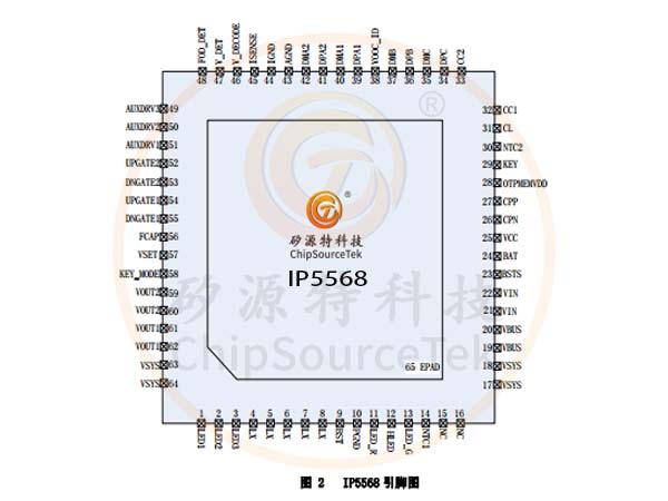
IP5568 Pin Definition:
IP Series Model Selection Table:
Mobile power IC

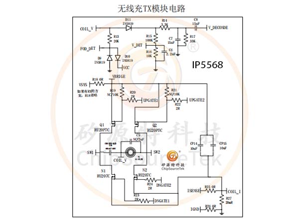
IP5568 Wireless Charging TX Module Circuit:
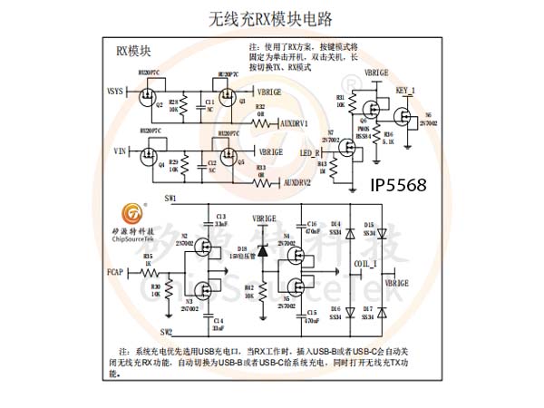
IP5568 Wireless charging RX module circuit:
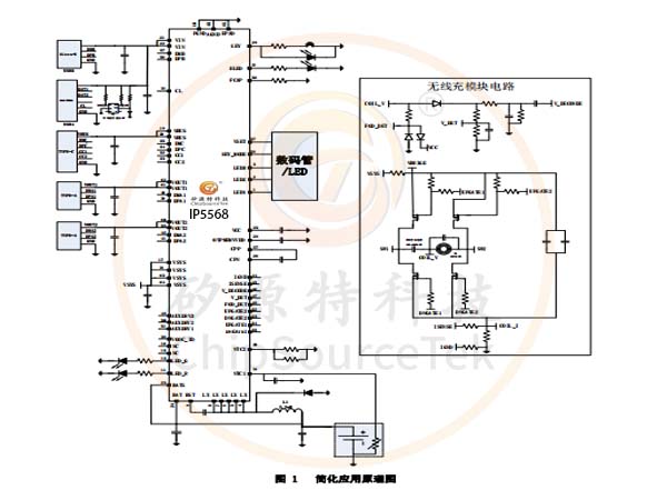
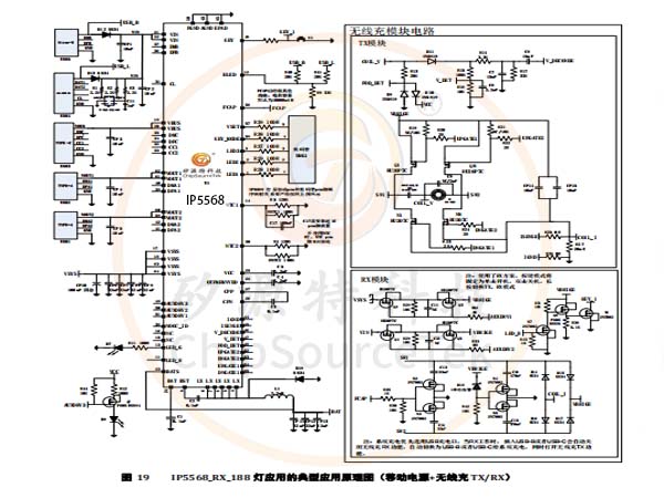
IP5568 Typical application schematic:
IP5568 only requires a small number of passive components such as MOS transistors, inductors, capacitors, resistors, etc. to achieve a fully functional fast charging mobile power supply solution.
Schematic diagram of mobile power bank+wireless charging TX+digital tube application:
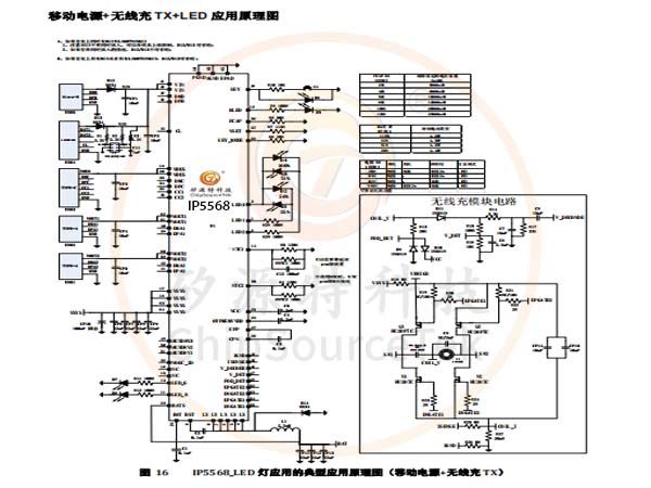
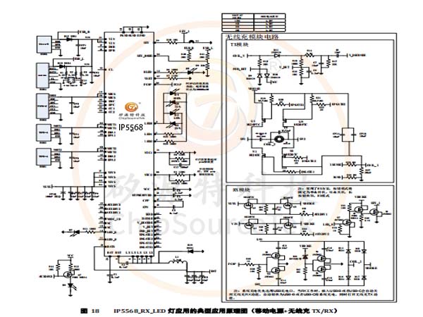
Schematic diagram of mobile power bank+wireless charging TX/RX+LED application:
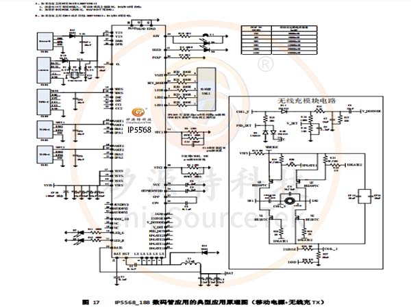
Schematic diagram of mobile power bank+wireless charging TX/RX+digital tube application:
IP5568 is a power management SOC that integrates wireless charging TX/RX, QC2.0/QC3.0/SCP/VOC output fast charging protocol, FCP/AFC/SFCP input/output fast charging protocol, MTK PE+1.1&2.0 output fast charging protocol, USB C/PD2.0/PD3.0 input/output protocol, USB C PD3.0 PPS output protocol, compatibility with BC1.2/Apple/Samsung phones, synchronous up/down converter, lithium battery charging management, battery level indicator and other functions, providing a complete power solution for fast charging mobile power banks. It can simultaneously support four USB ports: USB A x2, USB B, and USB C. Using any one USB port alone can support fast charging. When using two or more output ports simultaneously, it only supports 5V. IP5568 supports both wireless charging and USB port usage simultaneously.
The high integration and rich functions of IP5568 only require one inductor to achieve voltage reduction and boost functions, which requires very few peripheral devices in application, effectively reducing the size of the overall solution and lowering BOM costs.
The synchronous switch boost system of IP5568 can provide a maximum output capacity of 22.5W, and can maintain an efficiency of over 90% even when the battery voltage is low. Automatically enter sleep mode when unloaded.
The IP5568 synchronous switch charging system provides up to 5.0A charging current. Built in IC temperature, battery temperature, and input voltage control loop, intelligently adjusting charging current.
IP5568 has built-in USB C&PD2.0/PD3.0 protocols.
IP5568 has a built-in 14 bit ADC for precise measurement of battery voltage and current. IP5568 has a built-in battery level calculation method that can accurately obtain battery level information. Customizable battery level curve to accurately display battery level.
IP5568 supports 1/2/4 LED battery display, and supports various digital tube battery displays such as 88 and 188; Support lighting function; Support buttons.
IP5568 Features:
*Simultaneously supporting multiple USB ports and wireless charging
- 2 USB A ports for output, 1 USB B port for input
- 1 USB C-port input/output, 1 wireless charging TX/RX
*5W/10W/15W wireless charging transmitting and receiving unit
- Compatible with WPC v1.2.4 protocol, supporting 5w/7.5w/10w/15w wireless charging and transmitting specifications
- Support wireless charging 5w/10w receiving specifications
- Integrated MOS full bridge driver, integrated internal voltage/current demodulation
- Support FOD foreign object detection function
- Supports wireless transmission, wired output or input working simultaneously
- Supports single coil, double coil, and triple coil
*Fast charging specifications
- Either port supports fast charging
- Integrated QC2.0/QC3.0 output fast charging protocol
- Integrated FCP input/output fast charging protocol
- Integrated AFC input/output fast charging protocol
- Integrated SFCP input/output fast charging protocol
- Integrated SCP output fast charging protocol
- Integrated VOOC output fast charging protocol
- Integrated MTK PE+1.1&2.0 output fast charging protocol
- Integrated USB C DRP protocol, supports input/output fast charging
- Can support customization of 20W PDO
PDO:5V 2.4A、9V 2.22A、12V 1.67A
PPS 3.3V~11V 2A
- Compatible with BC1.2, Apple, Samsung phone fast charging
*Integrated USB Power Delivery (PD2.0/PD3.0) protocol
- Support PD2.0 bidirectional input/output protocol
- Supports PD3.0 input/output and PPS output protocol
- Supports 5V, 9V, 12V voltage range input and output
- PPS supports 5~11V, 20mV/step output voltage levels
- Bidirectional Label Encoding and Decoding (BMC) Protocol with Integrated Hardware
- Integrated Physical Layer Protocol (PHY)
- Integrated hardware CRC, supporting Hard Reset
*Charging specifications
- The maximum charging current at the battery end can reach 5.0A
- Adaptive charging current regulation
- Supports 4.20V, 4.3V, 4.35V, 4.40V batteries
*Discharge specifications
- Output current capability: 5V: 3.1A 9V: 2.0A 12V: 1.5A
- Customizable support for 20W output current capability
9V 2.22A 12V1.67A
- Synchronous switch discharge 5V 2A efficiency reaches over 95%
- Support line supplementation
*Battery level display
- Built in 14 bit ADC and battery meter
- Support 1/2/4 LED power display
- Support various digital tube battery displays such as 88 and 188
- Intelligent recognition of the number of LED power display lights
- Self learning battery meter with more uniform battery display
- Initial battery capacity PIN selection configuration
*Other functions
- Automatically detect phone insertion and removal
- Fast charging status indicator
- Support battery temperature detection and wireless charging temperature detection
- Intelligent load recognition, automatic standby mode for light loads
- Built in lighting driver
*Multiple protection, high reliability
- Input overvoltage and undervoltage protection
- Output overcurrent, overvoltage, and short-circuit protection
- Battery overcharge, overdischarge, overcurrent protection
- IC over temperature protection, NTC protection for charging and discharging battery temperature
- ESD 4KV, input (including CC pin) withstand voltage 20V
*BOM Minimalist
- Built in switch power MOS and path MOS
- Single inductor realizes charging and discharging functions
*Package specification: 8mm × 8mm 0.4pitch QFN64
IP5568 Application Products:
Mobile power bank with wireless chargingIP5568 Typical applications:
IP5568 Pin Definition:
IP Series Model Selection Table:
Mobile power IC
IC Model IP5303T IP5305T IP5306 IP5406T IP5407 IP5207 IP5207T IP5109 IP5209 IP5310 IP5506 IP5508 IP5330 IP5322P IP5332 IP5328P IP5358 IP5568 |  |
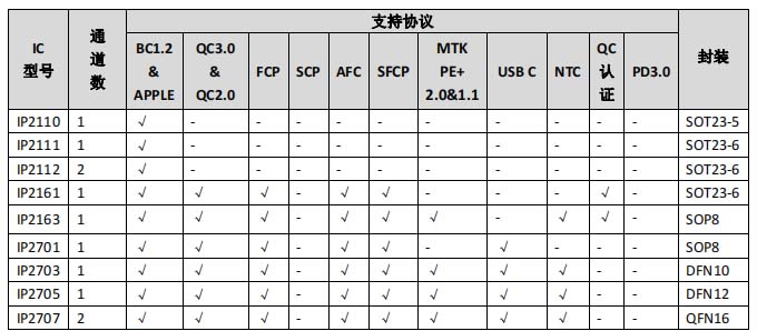
Protocol IC
IC Model IP2110 IP2111 IP2112 IP2161 IP2163 IP2701 IP2703 IP2705 IP2707 IP2716 |   |
IP5568 Wireless Charging TX Module Circuit:
IP5568 Wireless charging RX module circuit:
IP5568 Typical application schematic:
IP5568 only requires a small number of passive components such as MOS transistors, inductors, capacitors, resistors, etc. to achieve a fully functional fast charging mobile power supply solution.
Schematic diagram of mobile power bank+wireless charging TX+LED application:
Schematic diagram of mobile power bank+wireless charging TX+digital tube application:
Schematic diagram of mobile power bank+wireless charging TX/RX+LED application:
Schematic diagram of mobile power bank+wireless charging TX/RX+digital tube application:

Please submit your basic information, send an email to Sales@ChipSourceTek.com, or call us at 13823761625 (same number as WeChat), and we will contact you as soon as possible!

WeChat Official Account

WeChat Service
 Email
Email QQ
QQ 13823761625
