
Products
Products


NS2582
The NS2582 is a synchronous boost dual lithium battery charge management chip that supports 4-5.5V input voltage range with a maximum output of 2A current. The chip integrates MOSFETS with very low on-resistance to achieve high charging efficiency, and the chip requires only a few peripheral devices.
The NS2582 operates at 1.2MHz and integrates multiple protection functions to maximize the protection of chips and terminal devices. The charging current in CC mode can be changed by adjusting the resistance value of the RICHG resistor, and the constant voltage point of 8.4V or 8.7V can be selected by adjusting the CV pin. Chip built-in input adapter current limiting DPM function, through the external divider resistor set different VSEN voltage to match different adapters. Chip integrated temperature control loop, can intelligently adjust the charging current to control the chip temperature.
The NS2582 operates at 1.2MHz and integrates multiple protection functions to maximize the protection of chips and terminal devices. The charging current in CC mode can be changed by adjusting the resistance value of the RICHG resistor, and the constant voltage point of 8.4V or 8.7V can be selected by adjusting the CV pin. Chip built-in input adapter current limiting DPM function, through the external divider resistor set different VSEN voltage to match different adapters. Chip integrated temperature control loop, can intelligently adjust the charging current to control the chip temperature.
NS2582 Description:
The NS2582 is a synchronous boost dual lithium battery charge management chip that supports 4-5.5V input voltage range with a maximum output of 2A current. The chip integrates MOSFETS with very low on-resistance to achieve high charging efficiency, and the chip requires only a few peripheral devices.
The NS2582 operates at 1.2MHz and integrates multiple protection functions to maximize the protection of chips and terminal devices. The charging current in CC mode can be changed by adjusting the resistance value of the RICHG resistor, and the constant voltage point of 8.4V or 8.7V can be selected by adjusting the CV pin. Chip built-in input adapter current limiting DPM function, through the external divider resistor set different VSEN voltage to match different adapters. Chip integrated temperature control loop, can intelligently adjust the charging current to control the chip temperature.
The NS2582 also has a built-in charging status display function to determine the working status of the battery through the state of the LED. It also supports the normal operation of the synchronous boost function in battery-free mode.
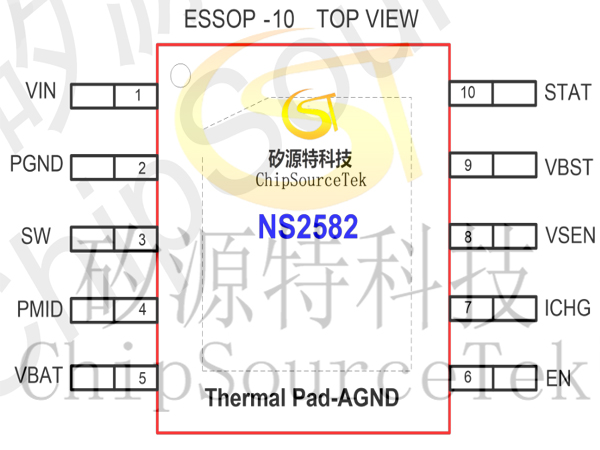
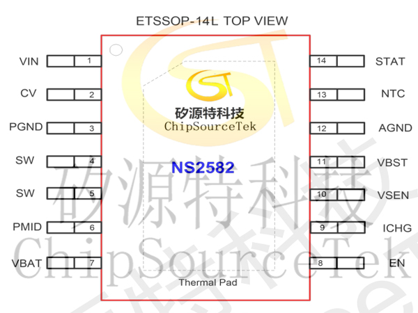
The NS2582 comes in a standard package of ESSOP-10 and ETSOP-14L.
The NS2582 operates at 1.2MHz and integrates multiple protection functions to maximize the protection of chips and terminal devices. The charging current in CC mode can be changed by adjusting the resistance value of the RICHG resistor, and the constant voltage point of 8.4V or 8.7V can be selected by adjusting the CV pin. Chip built-in input adapter current limiting DPM function, through the external divider resistor set different VSEN voltage to match different adapters. Chip integrated temperature control loop, can intelligently adjust the charging current to control the chip temperature.
The NS2582 also has a built-in charging status display function to determine the working status of the battery through the state of the LED. It also supports the normal operation of the synchronous boost function in battery-free mode.
The NS2582 comes in a standard package of ESSOP-10 and ETSOP-14L.
NS2582 Features:
Max 2A output synchronous switch type boost charger
The boost efficiency can be as high as 90%
Built-in battery short circuit/trickle/constant current/constant voltage mode
±0.5% battery constant voltage mode voltage accuracy
Support LED charging status indication
Support external adjustable charging current
Support input adapter DPM function
Disable the external EN function
Battery constant voltage mode 8.4V and 8.7V are optional
Thermal regulation and OTP temperature protection
Input voltage UVLO and OVP protection function
Output overvoltage and short circuit protection
Switching frequency: 1.2MHz, can support 1uH inductance
Built-in NTC battery temperature detection and enablement function
The boost function works properly in battery-free mode
ESSOP-10 and ETSOP-14L packages
NS2582 Application:
Bluetooth lithium battery application
Electronic cigarette
Portable lithium battery laptop
Lithium battery cell phone, PDA, MP3 and PM4 player
PSP and NDS portable game consoles, etc
Electronic cigarette
Portable lithium battery laptop
Lithium battery cell phone, PDA, MP3 and PM4 player
PSP and NDS portable game consoles, etc
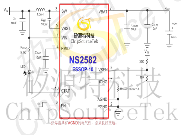
NS2582 Typical application circuit ESOP10:
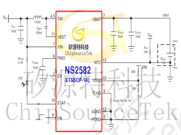
NS2582 Typical Application circuit ETSSOP-14L:
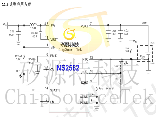
Typical application of NS2582:
NS2582 PCB Layout Suggestion
The PCB layout should follow the following rules to ensure the normal operation of the chip.
1, the power line (ground wire, SW line, VIN line) should be as short, straight and wide as possible;
2, VIN capacitor CVIN, inductor L and PMID capacitor CPMID should be placed as close to the pin as possible;
3, the switching tube loop area of the booster topology should be as small as possible, and the line should be as short as possible;
4. Increase the area of GND hot pad as much as possible to improve the heat conduction effect of the chip;
5, the power switch Node (SW Node) is usually a high-frequency voltage amplitude square wave, so it should be kept relatively small copper area, and the analog element should be far away
Off-power switch node area to prevent dopant capacitance noise;
6, the peripheral resistance of the circuit should be placed as close to the pin as possible, and away from the SW network line to avoid noise interference.
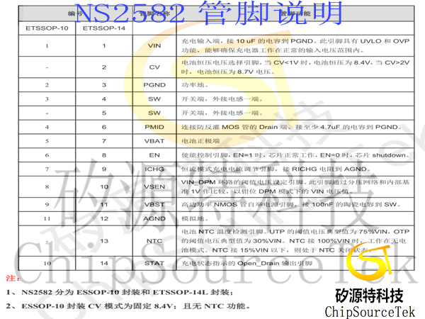
NS2582 Pin Configuration ESOP10:
NS2582 Pin configuration ETSSOP-14L:
NS2582 Pin Description:

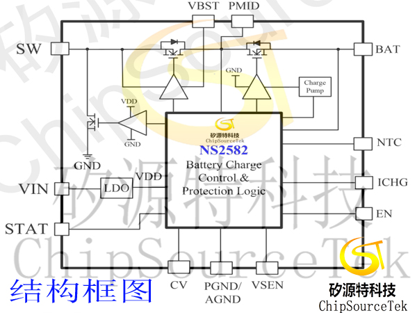
NS2582 structure block diagram:
NS2582 Function Description:
Basic functions of NS2582
The NS2582 is a synchronous boost dual lithium battery charge management chip that supports 4-5.5V input voltage range with a maximum output of 2A current. The NS2582 operates at 1.2MHz and integrates multiple protection functions. The chip can change the charging current in CC mode by adjusting the resistance value of RICHG resistor. The NS2582 features dynamic path management to set the threshold voltage triggered by the input DPM and limit the size of the input current value by connecting the VSEN pin to a divider resistor network to match different adapters. The NS2582 chip integrates MOSFETS with very low on-resistance to achieve high charging efficiency, and the chip requires only a few peripheral devices.
NS2582 Charging status indicator description
1. "Charging status" -- STAT pin is low;
2. "Full state" -- STAT pin is high;
3. "Error Status" - STAT pin flips high and low at 1Hz frequency. If the STAT pin is connected to the LED light to the VIN, the LED will be steady on during the charging state; In the full state, the LED is usually off; In the error state, the LED blinks at a frequency of 1Hz.
Description of the basic working mode of the booster charger in NS2582 switch mode
Working principle of NS2582
The NS2582 is an on-off mode boost charger with USB input. A fixed operating frequency of 1.2MHz is adopted to minimize the peripheral circuit design. When there is a battery, the NS2582 will work in short circuit mode, trickle mode, constant current mode and constant voltage mode according to the battery voltage. In battery-free mode, the load can be connected as a normal boost converter with integrated constant voltage and constant current loops.
NS2582 Protection principles
Multiple battery protection features are built into the NS2582. When the input overvoltage protection, output overvoltage protection, and thermal protection are triggered, the booster charger will immediately turn off the MOSFETS. When the battery voltage falls below VSHORT, triggering the short-circuit protection, the main power tube immediately shuts down and the chip charges at 50mA current. When the battery voltage is greater than VSHORT and less than VTRICKLE, the charger operates in light load mode, adjusts the PMID voltage to 6.8V, and charges at 100mA. When the battery voltage is higher than the VTRICKLE, the chip works in CC mode to charge the load.
NS2582 Input DPM working principle
The NS2582 has a built-in DPM function module to protect the device when the input DC source or adapter is overloaded. When overload occurs, a large charging current will lower the voltage value of the VIN, and the chip will detect the voltage value of the VIN compared to the SEN pin reference voltage. If the DPM function is triggered, the NS2582 will reduce the charging current and clamp the voltage of the VIN.
NS2582 constant voltage mode voltage selection
The NS2582 can set the voltage value of the battery constant voltage mode. When CV voltage is less than 1V, the constant voltage mode voltage is 8.4V. When the CV voltage is greater than 2V, the constant voltage mode voltage is 8.7V.
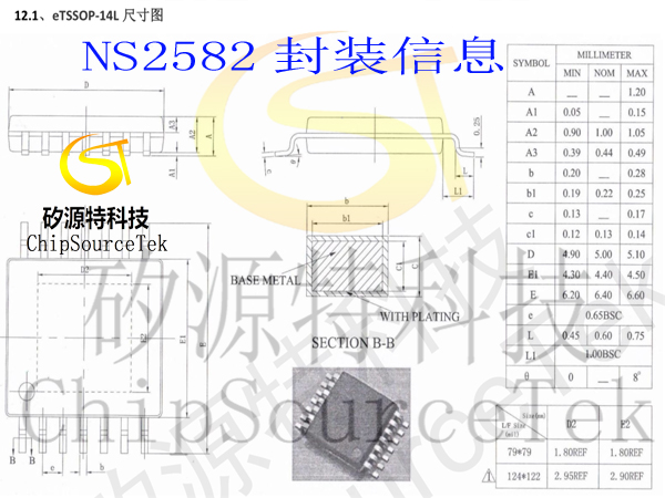
NS2582 Package information eTSSOP-14L
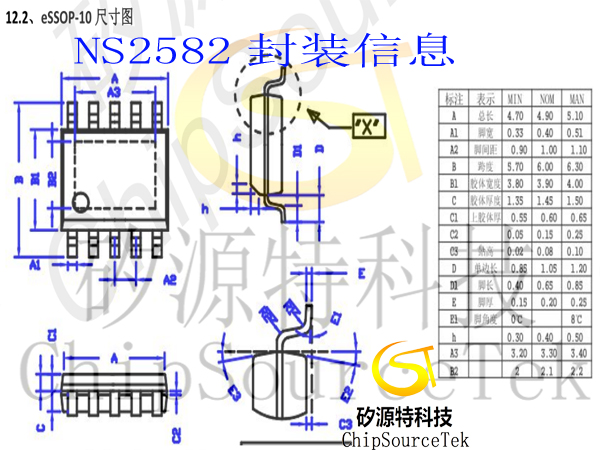
NS2582 Encapsulation information eSSOP-10

Please submit your basic information, send an email to Sales@ChipSourceTek.com, or call us at 13823761625 (same number as WeChat), and we will contact you as soon as possible!

WeChat Official Account

WeChat Service
 Email
Email QQ
QQ 13823761625
