
Products
Products
CN3085
The CN3085 is a core that can charge and manage nickel-metal hydride batteries, and can charge and manage single to four nickel-metal hydride batteries. The device includes a power transistor inside and does not require external current-detecting resistors and choke diodes. The CN3085 requires very few external components and is ideal for portable products. The heat modulation circuit can control the chip temperature within the safe range when the power consumption of the device is relatively large or the ambient temperature is relatively high. The chip is integrated with a high precision voltage comparator, which can accurately set the constant current charge termination voltage.
CN3085 Description:
The CN3085 is a core that can charge and manage nickel-metal hydride batteries, and can charge and manage single to four nickel-metal hydride batteries. The device includes a power transistor inside and does not require external current-detecting resistors and choke diodes. The CN3085 requires very few external components and is ideal for portable products. The heat modulation circuit can control the chip temperature within the safe range when the power consumption of the device is relatively large or the ambient temperature is relatively high. The chip is integrated with a high precision voltage comparator, which can accurately set the constant current charge termination voltage.
The CN3085 charging current can be set via an external resistor. When the input voltage is off, the CN3085 automatically enters the low-power sleep mode, and the current consumption of the battery is less than 3 microamps. Other functions include low input voltage latch, trickle charge when the battery is low voltage, automatic recharge, constant current charge, maintain charge (timing), cell temperature monitoring and status indication.
The CN3085 comes in a heat-enhanced 8-pin small form factor package (SOP8/PP).
CN3085 Features:
CN3085 Application:
CN3085 Pin function Description:
The CN3085 is a core that can charge and manage nickel-metal hydride batteries, and can charge and manage single to four nickel-metal hydride batteries. The device includes a power transistor inside and does not require external current-detecting resistors and choke diodes. The CN3085 requires very few external components and is ideal for portable products. The heat modulation circuit can control the chip temperature within the safe range when the power consumption of the device is relatively large or the ambient temperature is relatively high. The chip is integrated with a high precision voltage comparator, which can accurately set the constant current charge termination voltage.
The CN3085 charging current can be set via an external resistor. When the input voltage is off, the CN3085 automatically enters the low-power sleep mode, and the current consumption of the battery is less than 3 microamps. Other functions include low input voltage latch, trickle charge when the battery is low voltage, automatic recharge, constant current charge, maintain charge (timing), cell temperature monitoring and status indication.
The CN3085 comes in a heat-enhanced 8-pin small form factor package (SOP8/PP).
CN3085 Features:
On-chip power transistor
Voltage accuracy 1%
Trickle charging is used when the battery voltage is low
The user can set the charging current up to 1A
Constant current/constant temperature mode charging can maximize the charging current and prevent the chip from overheating
Automatically enters low-power sleep mode when the power supply voltage fails
The status indicator output can drive the LED or interface with the MCU
Maintain (timed) charging
Automatic recharge
Battery temperature monitoring function
Package form SOP8/PP
Products are lead-free, meet the rohs directive, halogen-free
CN3085 Application:
Digital camera
Electronic dictionary
Portable equipment
Application of Ni-MH battery charging
Electronic dictionary
Portable equipment
Application of Ni-MH battery charging
CN3085 Pin arrangement: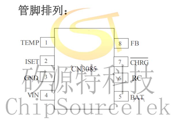
CN3085 Typical application circuit: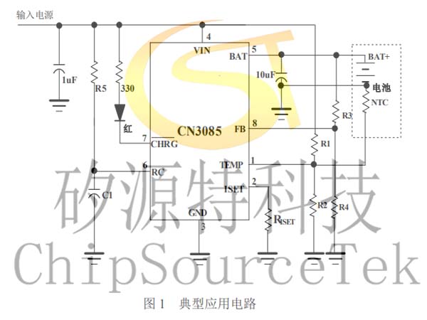
CN3085 Ordering Information:
Device type | Encapsulation form | Operating ambient temperature | package |
CN3085 | SOP8/PP | -40℃ 到 85℃ | Plate, 4000 pieces/plate |
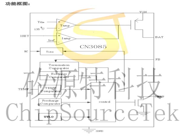
CN3085 function block diagram:
CN3085 Pin function Description:
Serial number | name | Function description |
1 | TEMP | Battery temperature monitoring input.Connect the TEMP pin to the output of the battery's NTC sensor. If the TEMP pin voltage is less than 45% of the input voltage or more than 80% of the input voltage, it indicates that the battery temperature is too low or too high. Charging is suspended, indicating that the battery is faulty. If TEMP is between 45% and 80% of the input voltage, the battery fault state will be cleared and charging will continue. If the TEMP pin is connected to the ground, the battery temperature monitoring function is disabled. |
2 | ISET | Constant current charging current setting terminal.The charging current can be set by connecting a resistor from the ISET pin to the ground end. In the trickle charging state, the voltage of the pin is modulated at 0.12V; In the maintained charging state, the voltage of this pin is modulated at 0.72V; In the constant current charging state, the voltage of this pin is modulated at 1.205V. Constant current charging current is determined by the following formula: ICH=1218V/RISET (A) In the trickle charging state, the charging current is 10% of the constant current charging current. In the maintained charging state, the charging current is 60% of the constant current charging current. |
3 | GND | electrically |
4 | VIN | Input voltage positive input end.The voltage of this pin is the working power supply of the internal circuit. When the voltage difference between VIN and BAT pin is less than 10mv, the CN3085 will enter the low-power sleep mode, and the current of BAT pin is less than 3uA. |
5 | BAT | Battery connection end.Connect the positive end of the battery to this pin, and the BAT pin provides charging current to the battery. In sleep mode, the current of the BAT pin is less than 3uA. |
6 | RC | Maintain charge timing Settings.In the constant current charging state, when the battery voltage reaches the constant current charging termination voltage, the constant current charging state ends, CN3085 enters the maintenance charging state, and charges the battery with the maintenance current, which is 60% of the set constant current charging current, and starts the maintenance charging timer at the same time. When the maintenance charging time ends, the whole charging process ends, and the charger enters the charging end state. The maintenance charge time is determined by the following formula: T = 2654 x R5 x C1+4980 x C1 x 103 Where, T is the timing time (unit: second). R5 unit is ohms, should be in 20k to 5M ohms, otherwise the timing accuracy may be affected C1 unit is farad, should be greater than 1nF, otherwise the timing accuracy may be affected. |
7 | CHRG | Charge status indicator for the open drain output.When CN3085 is in trickle charging state, constant current charging state and maintain charging state, CHRG pin is pulled to low level by internal switch, indicating that charging is in progress; Otherwise, the CHRG pin is in a high resistance state. |
8 | FB | Battery voltage feedback input.The voltage is fed back to the CN3085 through this pin, and the CN3085 determines the charging state according to the voltage of the FB pin. The corresponding relationship between FB pin voltage and battery terminal voltage is as follows: VBAT = VFB×(1+R3 / R4) |
9 | EP | The heat sink.Ground the heat sink. |

Please submit your basic information, send an email to Sales@ChipSourceTek.com, or call us at 13823761625 (same number as WeChat), and we will contact you as soon as possible!

WeChat Official Account

WeChat Service
 Email
Email QQ
QQ 13823761625
