XYT5080E Description:
The XYT5080E is a 5V USB adapter input, high-precision dual-section lithium-ion battery charge management chip. With 0V charging function, trickle charging, constant current charging, constant voltage charging and automatic cut-off, automatic recharge a complete charging cycle of charge management chip. The special 9V surge resistance inside the chip makes the chip application safer and more reliable.
The XYT5080E has a standard floating charge voltage of 8.40V, an ESOP8 package with a heat sink ground at the bottom, and an extremely streamlined external component, making the XYT5080E ideal for portable dual-section lithium-ion battery charging applications. The XYT5080E works with USB adapters or other 5V adapters, greatly reducing the cost of external accessories.
When the input voltage (USB power supply or AC adapter) is removed, the XYT5080E automatically enters a low current state, reducing the battery's leakage current to less than 1uA. Other features of the XYT5080E include undervoltage latching, adaptive adapter, automatic recharge, and an LED charging status indicator pin.
The XYT5080E is available in the ESOP8L standard package
XYT5080E function introduction and application points:
The XYT5080E is an asynchronous boost charging controller with 3.6V to 5.5V input and 1A output for dual lithium/lithium-ion battery charging. The boost switch charging converter operates at a frequency of 600Khz and has a perfect charge protection function. For different applications, the resistance value of the external resistance can be adjusted flexibly and easily, and the charging current can be set. Needle for different kinds of adapters, the chip built-in adaptive current adjustment loop, intelligent adjustment of charging current size, automatically match a variety of adapters. The chip places the power inside the tube, simplifies the peripheral circuit devices, and reduces the system cost.
Charging process
The XYT5080E uses a completed trickle/constant current/constant voltage charging mode. When VBAT < 2V, the system charges the lithium battery with 1/20 setting current and 0V charging mode; When 2V < VBAT < 5.6V, the system charges the lithium battery with 1/10 of the set current, which is trickle charging mode; When 5.6 < VBAT < 8.4V, the system charges with the set current, which is the constant current charging mode. When the battery voltage is close to 8.4V, charge for constant voltage mode; After entering the constant voltage charging mode, when the charging current is lower than 100mA, the system will stop charging and complete a full cycle of charging cycle. When the battery is full, the battery voltage drops below 8.2V and the system restarts to charge the battery, which is an automatic recharge function.
Protection function
XYT5080E has a complete lithium battery charging protection function. When the chip appears the input side overvoltage, output side overvoltage and overtemperature state, the boost charging state will be immediately closed. When the battery voltage is lower than VSHORT, the output undervoltage protection function is enabled and the main power tube is closed. The BLOCK tube will enter linear mode and charge the battery at 1/20 set current; When the battery voltage returns to VSHORT, the output short-circuit protection mode is closed, and the trickle mode is started.
Adaptive input current limiting power
XYT5080E built-in special loop, can automatically adjust the size of the charging current, prevent the charging current is too large and pull down the input voltage too much. When the voltage at the VSEN end is reduced to the threshold value of 1.2V, the adaptive loop will automatically adjust the duty cycle of the booster unit, and then adjust the size of the charging current to reduce the charging input pressure.
Enable function
In addition to the adaptive function, the VSEN terminal also has the enable function of the chip. When the VSEN voltage is lower than 0.4V, the chip is turned off.
Charging LED indicator
During the charging process, it is often bright and fully charged
If the input is overvoltage, the output is overvoltage or undervoltage, the output is overvoltage, the chip is overtemperature, or the battery is not connected, the indicator blinks at 1.3Hz.
XYT5080E Features:
10W, 2A input asynchronous switch boost charging
The boost charging efficiency is 90%
Automatically adjusts input current to match all adapters
Support LED charging status indication
Built-in power MOS, streamline peripheral circuits
600Khz switching frequency, can support 2.2uH inductance
Built-in output overvoltage, short circuit protection
Built-in input undervoltage and overvoltage protection
Built-in IC overtemperature protection
ESD 4KV electrostatic protection
The XYT5080E is available in the ESOP8L standard package
XYT5080E Application:
Bluetooth speaker
Electronic cigarette
walkie-talkie
Adult products
XYT5080E typical application diagram:
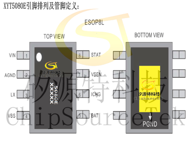
XYT5080E pin arrangement:
XYT5080E Pin definition:
.jpg)
XYT5080E functional block diagram: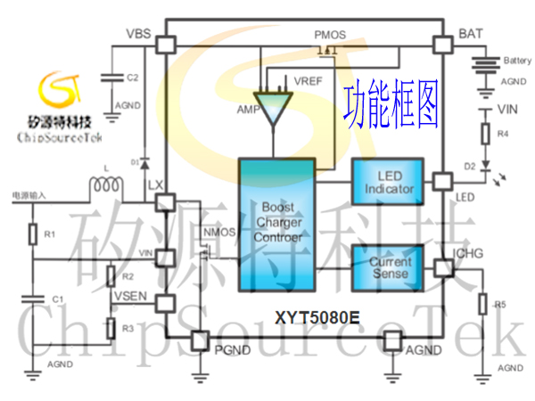
XYT5080E limit parameters:
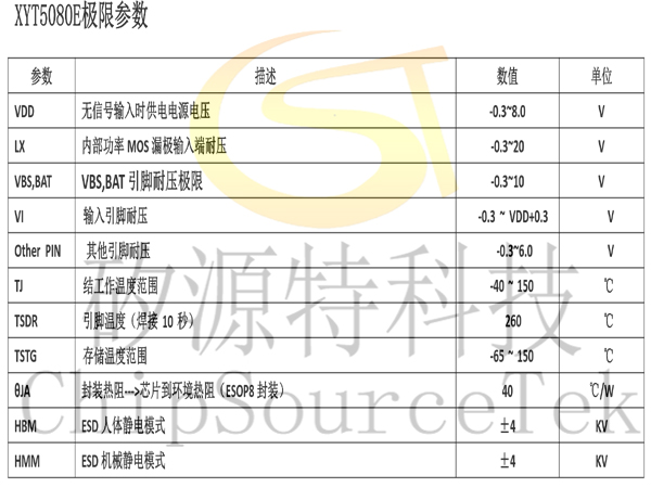
Note:
1. The above parameters are only the limit value of the device, and it is not recommended that the working conditions of the device exceed this limit value, otherwise it will affect the reliability and life of the device, and even cause permanent damage.
2. The PCB board needs a heat dissipation design to prevent XYT5080E, so that the heat sink at the bottom of XYT5080E is closely connected to the heat dissipation area, and it is a good choice to be closely connected to the bottom through multiple holes.
3. Special attention: the countervoltage generated during the operation of the inductive load of the motor will be relatively high, and the continuous current diode and electrolytic capacitor need to be added to the load power supply to filter out. Overload of abnormal voltage into the chip may cause permanent damage to the chip.
XYT5080E产品订购信息:


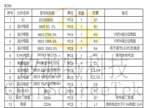
XYT5080E charging module circuit, BOM and PCB:

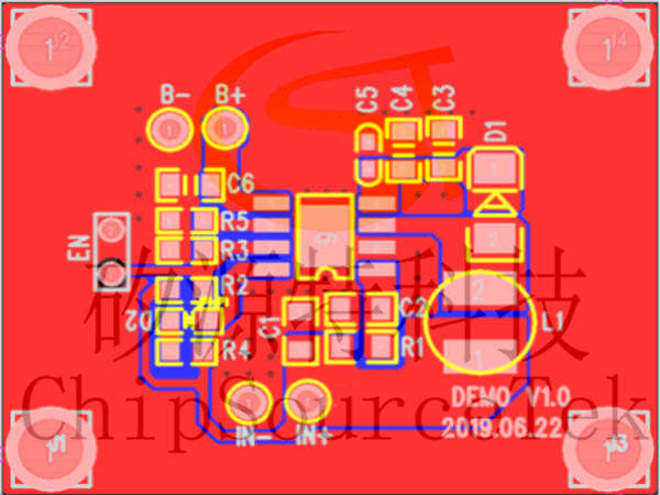
XYT5080E PCB wiring precautions: 1. The power cables should be as wide as possible and supply power to the XYT5080E separately.
2. The main current circuit of the BOOST module should be as short and thick as possible.
3. LX loop as short as possible, can effectively reduce EMI
4. Inductance and Schottky should be directly connected, short and thick, to avoid holes and jumpers
5. The capacitor at the power end should be as close to the chip as possible
6. The heat sink at the bottom of the chip is a power ground, which should be connected to the ground with solid copper, and the bottom heat sink and the ground should be reliably welded.
XYT5080E Product Application Answer:
1 Charging time is too long: charging time is usually too long due to the charging current is too small, or the battery capacity is too large (the maximum output charging current of the product is 1A)
Check the setting of the peripheral resistance of pin 6. For details, see the specification "Setting of charging current"
Check the pin voltage of the VIN. If the pin voltage of the VIN is low, the charging current is too small
Check the 7-pin VSEN voltage. If VSEN≤1.2V, the charging current will be automatically reduced. The pin can set the adaptive voltage
2. Insufficient charge: Measure the battery voltage after full charge 8.20V‐ 8.30V, can't reach 8.40V?
The floating charging voltage of this product is 8.40V, the accuracy is strictly in accordance with ±1%, that is, 8.316V‐ 8.484V range. When the lithium battery is close to full charge, the final floating charge voltage can be measured with a multimeter. Within the range of floating charging voltage, when the charging current slowly and automatically decreases to 1/10 of the set current, the chip determines that the battery is full and automatically turns off the charge.
After the full charge stops charging, the lithium battery loses the external charging voltage and current, the voltage of the lithium battery will not stay at the commanding height, determined by the characteristics of the lithium battery itself, there will be a little drop, and the amplitude of the lithium battery voltage drop with different internal resistance will have a certain difference.
3. Charging light flashing: There are five situations in which the lamp flashes during charging:
If the lithium battery is seriously over-discharged or short-circuiting, the battery voltage is lower than 2V, the 1Hz indicator blinks to indicate that the battery voltage is abnormal, and the battery is activated with 1/10 trickle current
The lithium ion battery is severely overvoltage (higher than 8.65V). If the 1Hz indicator blinks, the battery voltage is abnormal
The lithium battery is not connected to an open circuit, and no battery is detected
The charge protection chip does not match, the lithium battery voltage is not 8.4V, the protection circuit takes effect in advance, and the protection is automatically turned off
If the pairing of two batteries is abnormal, one battery triggers the protection circuit to take effect and automatically turns off the protection
4. Serious product heating:
A certain amount of heat will be generated during the booster charging process, which needs to be closely connected to the large area of copper skin of the PCB through the PAD at the bottom of the chip to dissipate heat in time.
In the LAYOUT, please try to increase the cooling area of the PCB, as much as possible to increase the amount of tin between the heat sink and the PCB, and make 6 to 9 small holes under the cooling PAD to connect to the bottom layer to enhance heat dissipation. PCB design should not design too many or too large holes, to prevent the solder paste through the hole to the bottom of the furnace, resulting in the loss of chip PAD solder paste.
The charging current is set to within 1A. If the PCB area is limited, the charging current setting can be adjusted appropriately.
5. Chip burning:
The input and output pin voltage of the chip is 10V, and too high external voltage may cause the chip to fail permanently. Possible causes of chip burning:
Input overvoltage: This product is specially designed for 5V adapters, input voltage limit up to 7V, please choose the appropriate adapter
The input surge voltage is too high: the input surge withstand voltage is 10V. If the surge is abnormally high during insertion or use, you need to add filtering methods to solve the problem
Output overvoltage: The output voltage can withstand 10V, and too high external voltage may cause permanent failure of the chip
The output surge voltage is too high: pay special attention to the inductive load circuit of the motor, when the motor is disconnected or positive and negative instantaneous will produce a large reverse peak voltage, much higher than the power supply voltage, for the motor with single direction rotation, a parallel current diode at both ends of the motor is the best measure; Bidirectional rotation, it is not good to use a continuous current diode, you can parallel a non-polar capacitor at both ends of the motor, and you can increase large-capacity capacitance absorption at the power end.
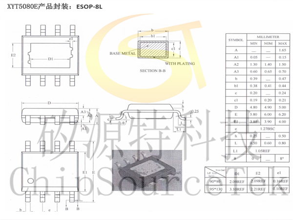
XYT5080E product package: ESOP-8L


.jpg)

.jpg)


.jpg)


 Email
Email QQ
QQ 13823761625
