
矽源特ChipSourceTek-CST6115重塑小型电机控制
Breakthrough Drive Solution: How does ChipSourceTek-CST6115 Reshape Small Motor Control with 12V/4A Performance?
I、Core parameters and industry positioning
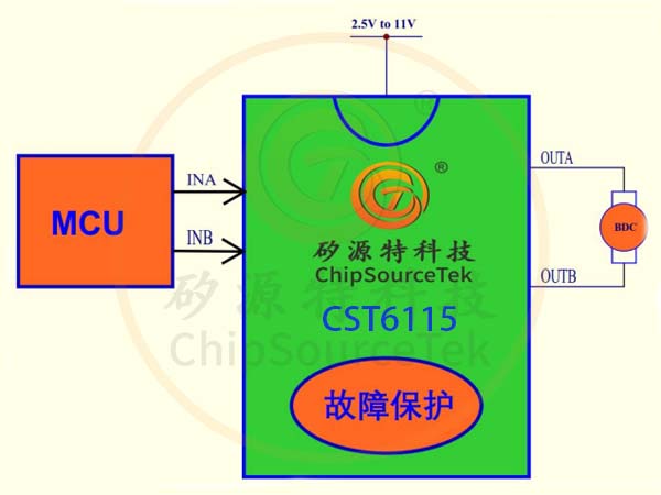
ChipSourceTek-CST6115 is a highly efficient driver chip specifically designed for brushed DC motors. Its wide voltage operating range of 2.5V to 12V (with a maximum withstand voltage of 15V) covers a wide range of scenarios from portable devices to industrial control. This chip offers a continuous operating current of 2.1A and a peak transient output capability of 4A, meeting the high-load requirements such as motor start and stop, and locked rotor. As an innovator in the field of motor driver chips, ChipSourceTek-CST6115 has been successfully applied to high-end devices such as smart homes, robot joints, and electronic locks, achieving precise bidirectional control of motors through an H-bridge architecture.
Ii. Analysis of the Eight Core Technological Advantages
Intelligent power topology
It adopts a four-channel N-MOSFET H-bridge drive architecture and significantly reduces power consumption through a low on-resistance (Rds(on)) design. Compared with traditional discrete solutions, the integrated design reduces the PCB footprint by 70% and supports a PWM speed regulation response up to 10kHz.
Dynamic current management
The unique current Decay Mode can intelligently adjust the energy release of the motor winding. When a sudden load change is detected, the chip automatically switches between fast attenuation and slow attenuation modes to avoid mechanical vibration caused by speed fluctuations.

Triple safety protection
Overcurrent protection (OCP) : Real-time monitoring of MOSFET current, and immediate shutdown triggered by a 4A peak threshold
Under-voltage lockout (UVLO) : Forces into sleep mode when the input voltage drops below 2.3V to prevent logical errors
Overheat shutdown: Protection is activated when the junction temperature exceeds 150℃ and automatically recovers after cooling
Revolution in Energy Consumption Control
Support μ A-level sleep mode: When the dual logic input pins (IN1/IN2) remain at A low level for more than 1ms, the quiescent current drops to the microampere level, extending the standby time of battery-powered devices by five times.
Iii. In-depth adaptation to industry application scenarios
- In the field of smart door locks: Utilizing 12V voltage compatibility to directly drive the lock tongue motor, the peak current ensures that the opening and closing actions are completed within 0.3 seconds

Service robot joint: 2.1A continuous current supports high-torque servo, PWM speed regulation achieves 0.1° precise positioning
Medical equipment pump: Reduce electromagnetic interference (EMI) below FCC Class B standard through the ripple suppression scheme on page 8 of the PDF data sheet
Iv. Design Practice Guidelines

Key points of layout
- The length of the power loop path (VM-GND) should be less than 10mm to avoid voltage spikes caused by parasitic inductance
- The heat dissipation pads must be connected to a copper foil area of ≥4×4cm² (thermal resistance θja < 40℃/W).
Typical troubleshooting
If the motor experiences starting and stopping jitter, it is necessary to check whether the IN1/IN2 pins meet the requirements
①PWM duty cycle > 15% (maintaining the minimum drive voltage)
② Rise/fall time < 500ns (to avoid MOSFET half-conduction)

五、Competitive performance comparison
| Parameter | CST6115 | Industry average | Margin of advantage |
|-----------------|---------------|-------------|----------|
| Operating voltage range | 2.5V-12V | 3V-9V | +33% |

| Peak driving capability | 4A | 2.8A | +43% |
| Sleep current | <1μA | 50μA | -98% |
| Protection response time | 200ns | 1μs | Five times faster |
Get the complete technical solution immediately
As the preferred choice for enterprise-level motor driver chips, CST6115 has passed the IEC 62368-1 safety certification. Click to download the authoritative data manual: CST6115 Complete Specification sheet, to obtain the motor drive parameter calculation tool, reference design schematic diagram and EMC optimization plan. Contact the Silicon Source technical support team to apply for free samples and customized driver solution evaluations.

WeChat Official Account

WeChat Service
 Email
Email QQ
QQ 13823761625
