
In the design of audio power amplifier systems, how to achieve a cost-effective stereo solution has always been the focus of engineers' attention. This article will provide a detailed introduction on how to build a 2x10W dual-channel boost solution using two ChipSourceTek-CST8337 chips. This solution not only features excellent performance but also significantly reduces system costs and PCB area occupation.
1. Overview of the Plan
ChipSourceTek-CST8337 is a highly efficient audio power amplifier chip in the ESSOP-10 compact package. Its most distinctive feature is the integration of a boost converter function. By ingeniously leveraging the collaborative work of two ChipSourceTek-CST8337 chips, a dual-channel output power of 2x10W can be achieved. The core innovation of this solution lies in the fact that only one set of boost peripheral circuits is needed to provide sufficient power supply capacity for the two channels. The specific implementation method is to have the boost output of the first ChipSourceTek-CST8337 simultaneously supply power to the second chip, thereby eliminating the need for a second boost circuit.
2. Analysis of Scheme Advantages
2.1 Spatial optimization
The two ChipSourceTek-CST8337 chips are packaged in ESSOP-10, occupying only approximately 20mm² of the board area. Compared with traditional solutions, they can save more than 30% of the PCB space. This compact design is particularly suitable for portable devices or applications with limited space.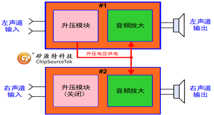
2.2 Cost advantage
Due to the elimination of a boost circuit (including inductors and Schottky diodes), the material cost can be reduced by approximately 15%. Meanwhile, the simplified BOM table also reduces the complexity of procurement and inventory management.
2.3 Performance characteristics
This solution supports the switching of AB/D class working modes, solving the problem that high-power dual-channel solutions in the market lack AB class options. Class AB mode has lower distortion at medium and low volumes, while Class D mode can offer higher efficiency. In addition, the chip has an instantaneous input current capability of 8A, fully meeting the power requirement of 10W×2 for dual-channel systems.
3. Detailed circuit design
3.1 Key connection method
- The VCTRL (Pin3) of the two chips needs to be connected in parallel as the system enable control terminal
- The first chip (#1) requires a complete peripheral boost circuit, and its boost output HPVDD is directly connected to the HPVDD (Pin9) of the second chip (#2).
- The pins 6, 7 and 8 of the second chip remain suspended
3.2Important parameter Settings
- The current limiting resistor Rlim is recommended not to exceed 43kΩ
- The ILIMIT pin bypass capacitor is recommended to be ≥1uF. A capacitance value that is too small may cause an excessive starting current
- When switching modes, it is necessary to ensure that the enable control remains off for at least 100ms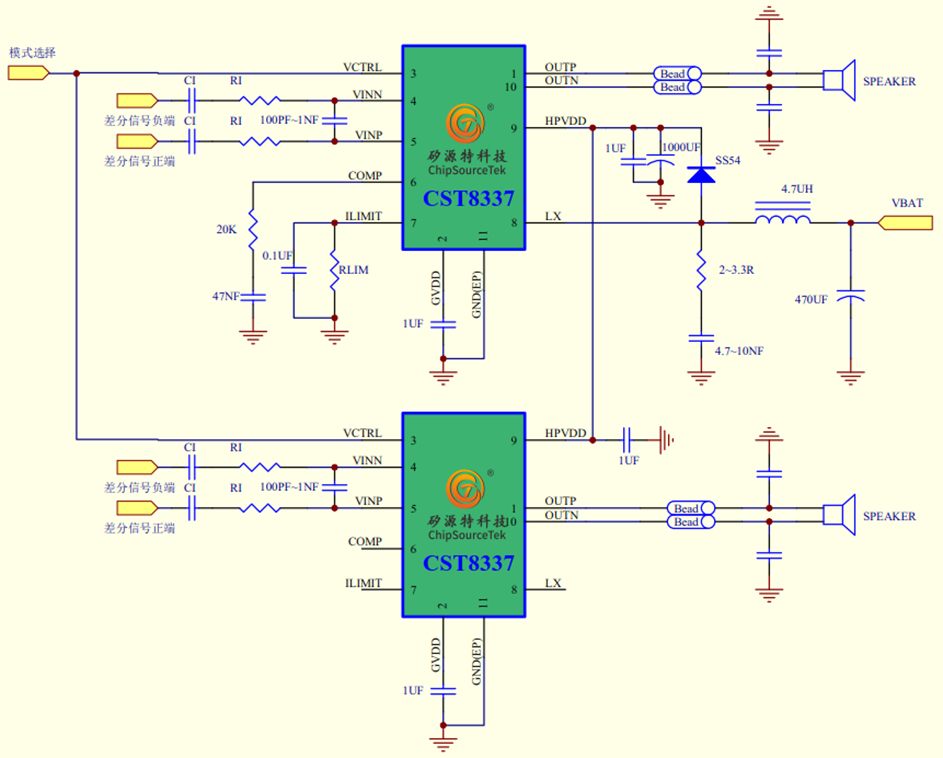
4. Performance parameters
Test under the conditions of AV=26dB, TA=25℃, and VBAT=3.7V:
- Total harmonic distortion (THD+N) <0.1% (at 1W output)
- Channel separation degree >70dB
- Efficiency can reach up to 85% (Class D mode)
- Operating voltage range: 2.5V-5.5V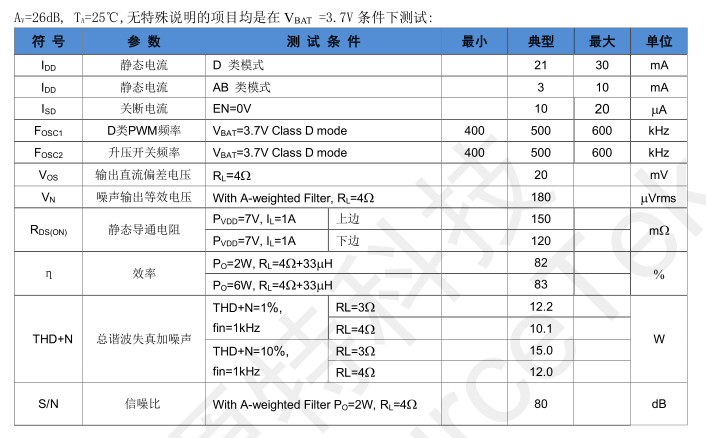
5. Practical application suggestions
5.1 Key points of PCB layout
- The boost induction should be placed as close as possible to chip #1
- The power traces need to be wide enough, and it is recommended that they be no less than 20mil
- Special attention should be paid to avoiding parallel routing with other sensitive signals in HPVDD routing
5.2 Thermal management considerations
Although the ESSP-10 package has good heat dissipation performance, attention should still be paid when it is output at full power:
- Make sure there is enough copper sheet area to help with heat dissipation
- Heat dissipation vias can be added when necessary
- When the ambient temperature is high, the output power should be appropriately reduced
5.3 Debugging skills
- It is recommended to test with a low voltage (such as 3V) for the first power-on
-Use an oscilloscope to observe the rising waveform of HPVDD to ensure there is no overshoot
-The current limit value can be gradually adjusted through the ILIMIT resistor
6. Scheme comparison
Compared with the traditional dual-chip solution, this solution has obvious advantages:
-The number of peripheral components has been reduced by 40%
-The PCB area is saved by 30%
-The system efficiency has been increased by 5-8%
-The cost is reduced by 15-20%
7. Typical application scenarios
This solution is particularly suitable for the following applications:
- Portable Bluetooth speaker
- Smart home central control device
-In-vehicle entertainment system
- Laptop audio system
- Smart TV audio system
8. Design considerations
8.1 Power Supply Integrity
Special attention should be paid to the shared boost circuit:
- The HPVDD traces should be thick enough
- Place a sufficient capacity energy storage capacitor near the HPVDD pin of chip #2
- Avoid voltage drop caused by long-distance wiring
8.2 Signal integrity
- The audio input traces should be kept away from the power traces
- It is recommended to use differential wiring to transmit audio signals
- Add EMI filter components appropriately
9. Troubleshooting Guide
Common Problems and Solutions
9.1 No sound output
- Check whether the heat dissipation conditions are sufficient
-Reduce the output power or switch to Class D mode
- Confirm that the ambient temperature is within the allowable range
9.2 Insufficient output power
- Check whether the VBAT voltage meets the standard
- Confirm that the current limiting resistance value is appropriate
- Measure the voltage drop of HPVDD at full load
9.3 Overheat protection triggered
- Check whether the heat dissipation conditions are sufficient
-Reduce the output power or switch to Class D mode
- Confirm that the ambient temperature is within the allowable range
10. Solution scalability
This basic solution can be further expanded:
- Add DSP for audio effect processing
- Integrated Bluetooth receiving module
- Add a digital input interface
- Achieve multi-room audio synchronization
In summary, this dual-channel boost solution based on two ChipSourceTek-CST8337 chips, through an innovative power supply architecture design, ensures audio performance while optimizing cost and space. Its flexible AB/D class switching function, outstanding energy efficiency performance and compact package size make it an ideal choice for medium and high power portable audio devices. Engineers only need to pay attention to the key points mentioned in this article when designing, and they can quickly implement a high-performance stereo audio solution.

WeChat Official Account

WeChat Service
 Email
Email QQ
QQ 13823761625
