The CST6118 provides a SOP8 motor drive chip for single-channel forward and reverse peak 2.5A continuous 1.8A.
The full bridge drive architecture and drive mode can save peripheral filter circuit, save cost and facilitate application. Very small circuit static power consumption (less than 1uA), low on-resistance (0.4Ω/1000mA), wide operating voltage operating voltage range (1.5V~7.2V), can make the CST6118 more widely used.
The CST6118 is available in a SOP8 package.
Operating voltage range (1.5V~7.2V)
Maximum continuous output current up to 1.8A
Maximum peak output current up to 2.5A
Includes forward/reverse/stop/brake and other functions
Very low static current (typ.0.1uA)
Built-in Thermal protection with hysteresis (TSD)
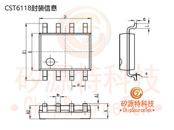
The CST6118 is available in a SOP8 package
Electric toothbrush
Electronic lock
Toy motor drive
Car mount
Remote control car
Adult sex toys
Car mount

Note:
1. The C4/104P capacitor in the figure is connected in parallel to the motor rather than placed on the PCB. If the motor is not connected in parallel, a position can be reserved on the PCB.。
2. Compared to the general application of similar products in the market, C1, C2, and C3 in the figure can be omitted, reducing peripheral devices and saving costs.
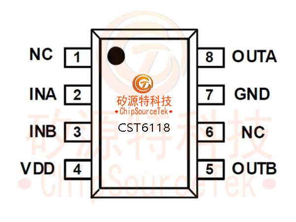
| Serial number | Pin name | Input/output | Pin specification |
| 1 | NC | -- | Free foot |
| 2 | INA | I | Control signal A input |
| 3 | INB | I | Control signal B input |
| 4 | VDD | I | Power source |
| 5 | OUTB | O | Driver B output |
| 6 | NC | -- | Free foot |
| 7 | GND | I | GND |
| 8 | OUTA | O | Drive a output |
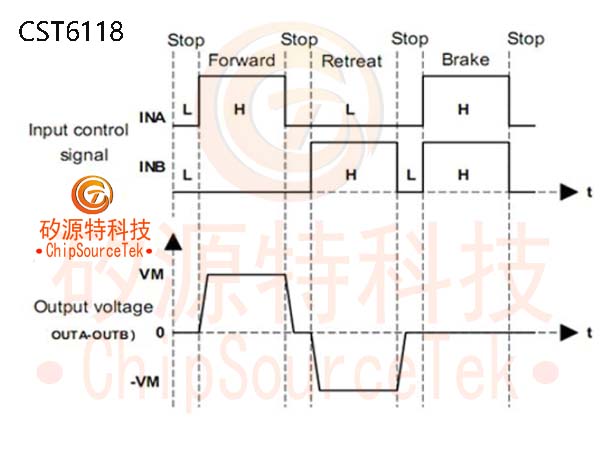
CST6118 Typical waveform diagram:
CST6118 Package information:
The full bridge drive architecture and drive mode can save peripheral filter circuit, save cost and facilitate application.
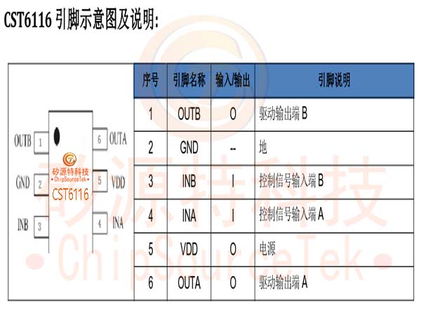
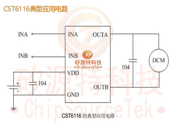
The CST6116 has thermal protection with hysteresis effect and has a very small circuit static power consumption (less than 1uA).
Single channel full bridge drive circuit
Operating voltage range (1.5V~6V)
Low standby current (typ.0.1uA)
There are four functions: forward/reverse/stop/brake
Built-in overheating Protection circuit with hysteresis (TSD)
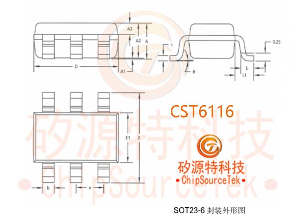
Package form: SOT23-6
Toy cars are driven by motors
Toy airplane tail motor drive
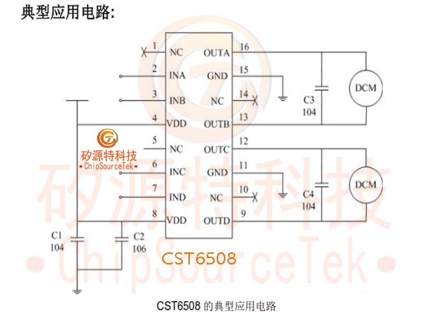
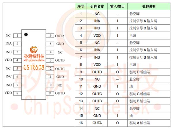
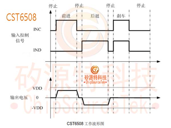
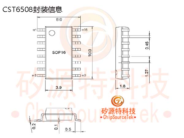
The CST6508 provides a SOP16 motor drive chip for dual-channel forward and reverse peak 2.5A continuous 1.8A.
Operating voltage range (1.5V~7V)
Maximum continuous output current up to 1.8A
Maximum peak output current up to 2.5A
Includes forward/reverse/stop/brake and other functions
Very low static current (typ.0.1uA)
Built-in Thermal protection with hysteresis (TSD)
Package format: SOP16
Toy DC brush motor drive
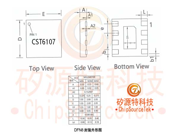
The CST6107 provides a DFN2*2_8L motor drive chip for single-channel forward and forward rotation peak 2.5A sustained 1.58A.
CST6107 Feature:
Working voltage range (1.5V~7V)
The maximum continuous output current can reach 1.8A
The maximum peak output current can reach 2.5A
Includes functions such as forward/reverse/stop/brake
Extremely low static current (typ. 0.1uA)
Low on resistance (0.4 Ω/1000mA)
Built in thermal protection function with hysteresis effect (TSD)
Packaging form: DFN8-2mm * 2mm * 0.55mm
CST6107 Application:
Micro robot equipment
Electric toothbrush
Electronic lock
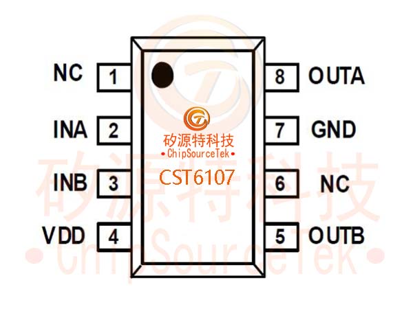
CST6107 Pin diagram and explanation:
Serial number | Pin name | Input/Output | Pin Description |
1 | NC | -- | Hanging feet |
2 | INA | I | Control signal A input terminal |
3 | INB | I | Control signal B input terminal |
4 | VDD | I | Power Supply |
5 | OUTB | O | Drive B output terminal |
6 | NC | -- | Hanging feet |
7 | GND | I | land |
8 | OUTA | O | Drive A output terminal |
CST6107 Typical Application Circuit:
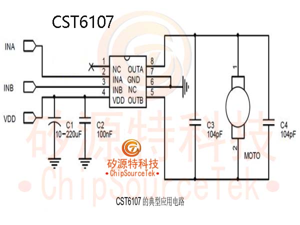
2. Compared to similar products on the market, C1, C2, and C3 in the diagram can generally be omitted, reducing peripheral components and saving costs.
INA | INB | OUTA | OUTB | Function |
L | L | Hi-Z | Hi-Z | Standby mode |
H | L | H | L | Forward |
L | H | L | H | Back off |
H | H | L | L | Brake |

.jpg)
.jpg)
.jpg)
